Battery holder for a driving tool

a technology of battery holder and driving tool, which is applied in the direction of portable power-driven tools, cell components, coupling device connections, etc., can solve the problems of greatly restricted transmission of vibration or impact to the battery holder, and achieve the reduction of vibration or impact transmitted to the battery pack, simple and inexpensive configuration, and the effect of reducing the transmission of vibration or impa

Active Publication Date: 2012-02-28
MAKITA CORP
View PDF22 Cites 18 Cited by
  • Summary
  • Abstract
  • Description
  • Claims
  • Application Information

AI Technical Summary

Benefits of technology

[0008]According to a first aspect of the invention, a battery pack is attached to a battery holder supported in a floating state with regard to the tool main body via an elastic material, electrically connected via this battery holder with regard to the tool main body, and attached so that the battery pack may not fall off. And thus, the vibration or the impact as a force of reaction caused by a striking movement at the tool main body side is absorbed by the elastic material, and transmission of the vibration or impact to the battery holder is greatly restricted. As a result, an electrical contact and an attaching state of the battery pack with respect to the battery holder can be maintained satisfactorily.
[0009]According to a second aspect of the invention, the battery holder can be supported in a floating state with regard to the tool main body in a simple and an inexpensive configuration.
[0010]According to a third aspect of the invention a nail feed direction is configu

Problems solved by technology

And thus, the vibration or the impact as a force of reaction caused by a striking movement at the tool main body side is

Method used


Image

  • Battery holder for a driving tool
  • Battery holder for a driving tool
  • Battery holder for a driving tool

Examples


Embodiment Construction

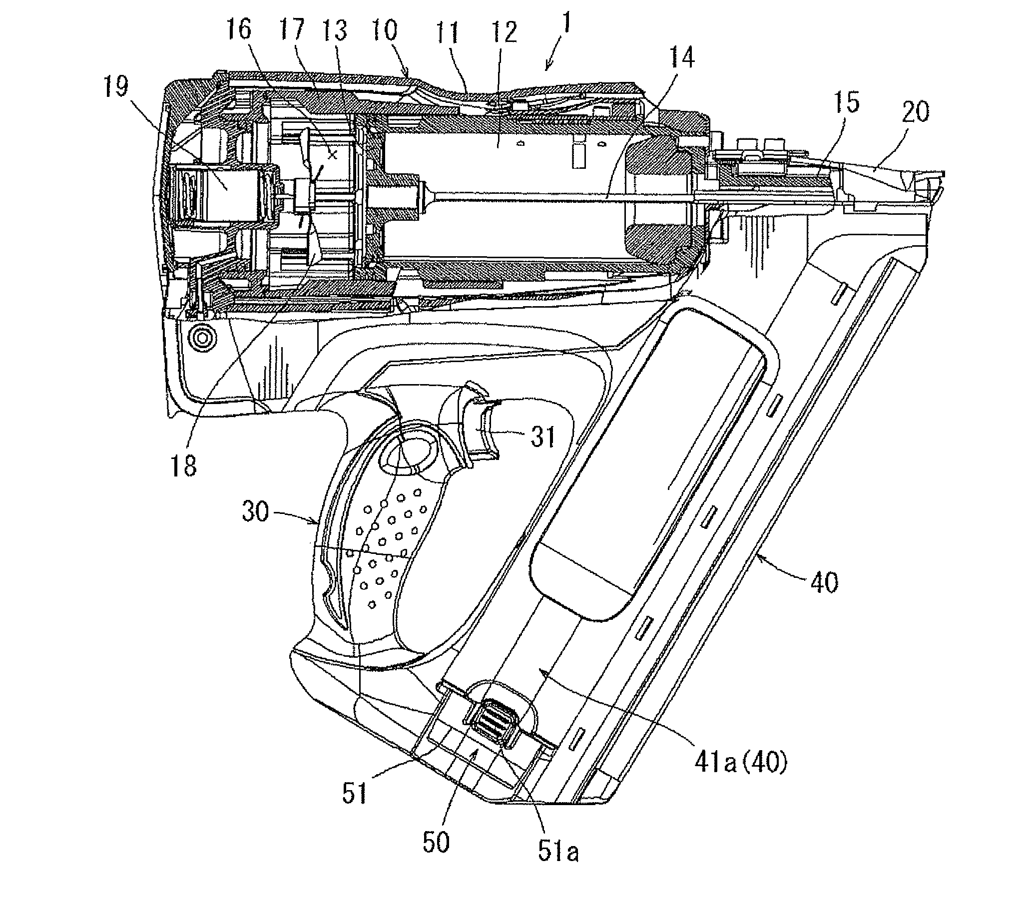
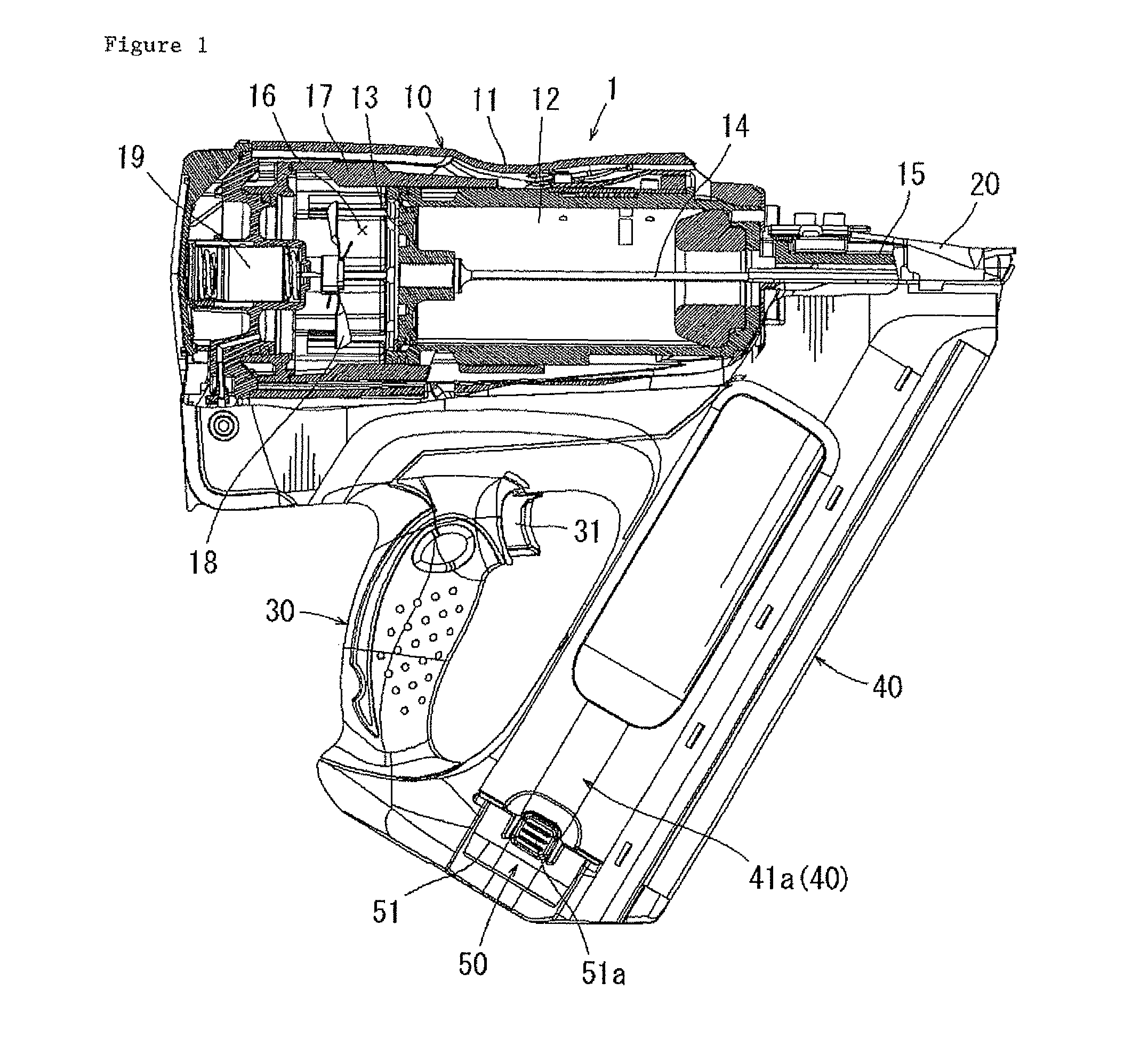
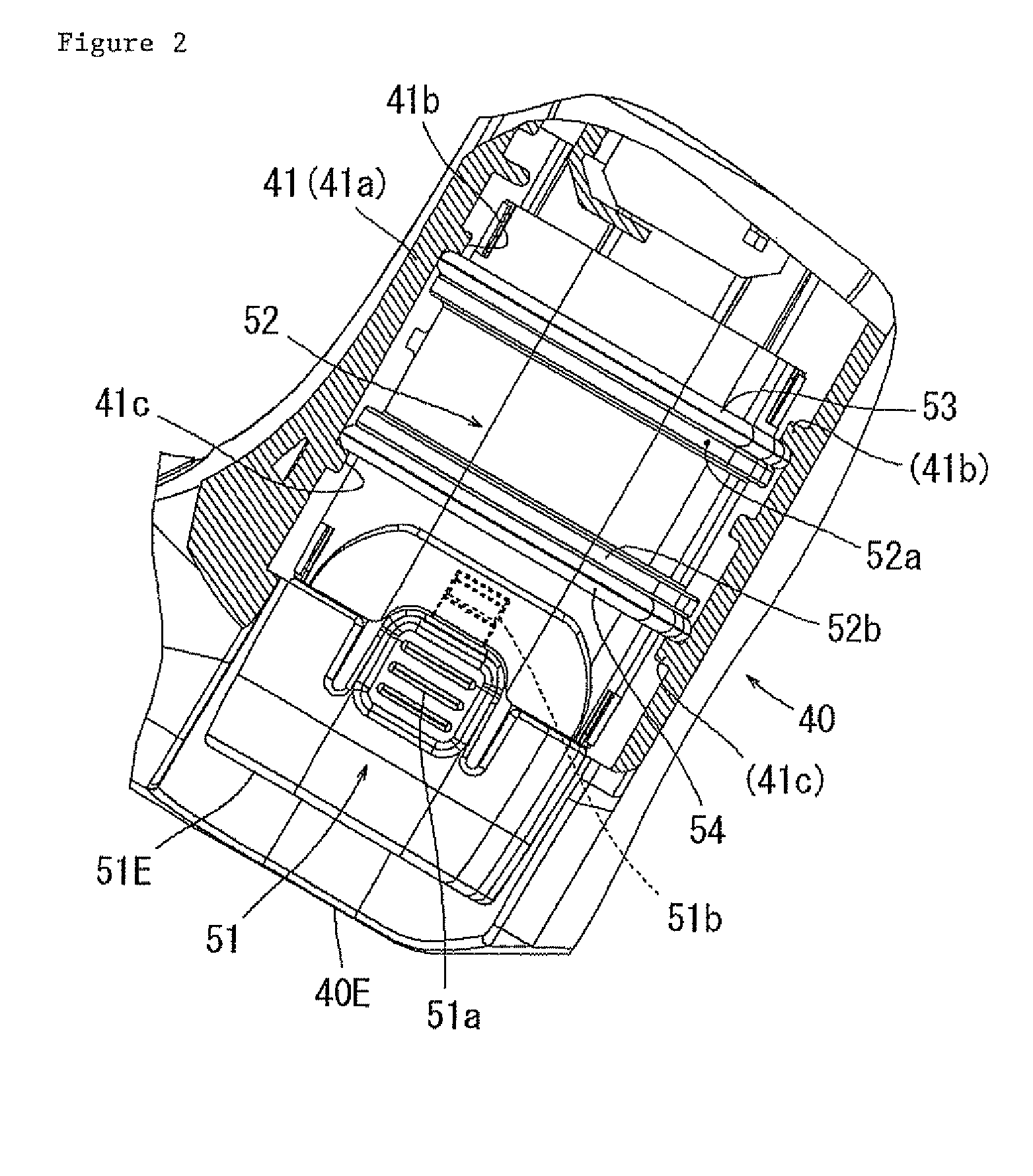
[0016]Next, an embodiment of the present invention will be described with reference to FIG. 1 to FIG. 4. In this embodiment, a gas combustion type nail driver is illustrated as an example of a driving tool. FIG. 1 shows an overall driving tool 1 according to this embodiment. This driving tool 1 includes a tool main body 10, a handle portion 30 provided in a state in which it protrudes laterally from the lateral part of the tool main body 10, and a driven-members-housing magazine 40 provided to extend between a distal end portion of the tool main body 10 and a distal end portion of the handle portion 30. A battery pack 51 is attached to the distal end portion of this driven-members-housing magazine 40 (a rear end portion with respect to a feed direction of driven members, a lower end portion in FIG. 1). The embodiment is characterized in the attachment configuration of this battery pack 51, and a basic configuration of the driving tool 1 such as the tool main body 10 requires no part...


PUM

PropertyMeasurementUnit
Shapeaaaaaaaaaa
Elasticityaaaaaaaaaa

Abstract

Vibration or the impact of a tool main body may be blocked by the support of a battery holder via elastic materials in a floating state at the rear end portion side in a feed direction of a driven-members-housing magazine and by the attachment of a battery pack to this battery holder.

Description

BACKGROUND OF THE INVENTION[0001]1. Field of the Invention[0002]The present invention relates to a driving tool equipped with a rechargeable battery pack as a power source, for example, a gas combustion type driving tool for driving nails.[0003]2. Description of the Related Art[0004]For instance, as a driving tool such as a nail driver, a gas combustion type driving tool, which strikes driven members by reciprocating a piston with gases exploded in a combustion chamber, has been proposed as well as a driving tool using compressed air as a driving source. In the case of this gas combustion type driving tool, a fan is provided in a combustion chamber in order to stir the gases supplied into the combustion chamber and air introduced from outside to the combustion chamber in an appropriate ratio or to accelerate evacuation from the combustion chamber after combustion (after striking driven members). This fan in the combustion chamber rotates with an electric motor as a drive source. Thi...

Claims


Application Information

Patent Timeline
IPC IPC(8): B25C1/18B25C7/00
CPCB25C1/08B25F5/02B25F5/006
Inventor MIYATA, KENICHI
Owner MAKITA CORP
Why Eureka
Try Eureka