Disposable centrifugal blood pump with magnetic coupling
a centrifugal blood pump and magnetic coupling technology, which is applied in the direction of positive displacement liquid engines, circulatory assistance devices, intravenous devices, etc., can solve the problems of heat generation, increased manufacturing costs, and difficult to ensure reliability, so as to reduce the cost of disposable parts, and reduce the magnetic resistance of the magnetic circuit.
- Summary
- Abstract
- Description
- Claims
- Application Information
AI Technical Summary
Benefits of technology
Problems solved by technology
Method used
Image
Examples
first embodiment
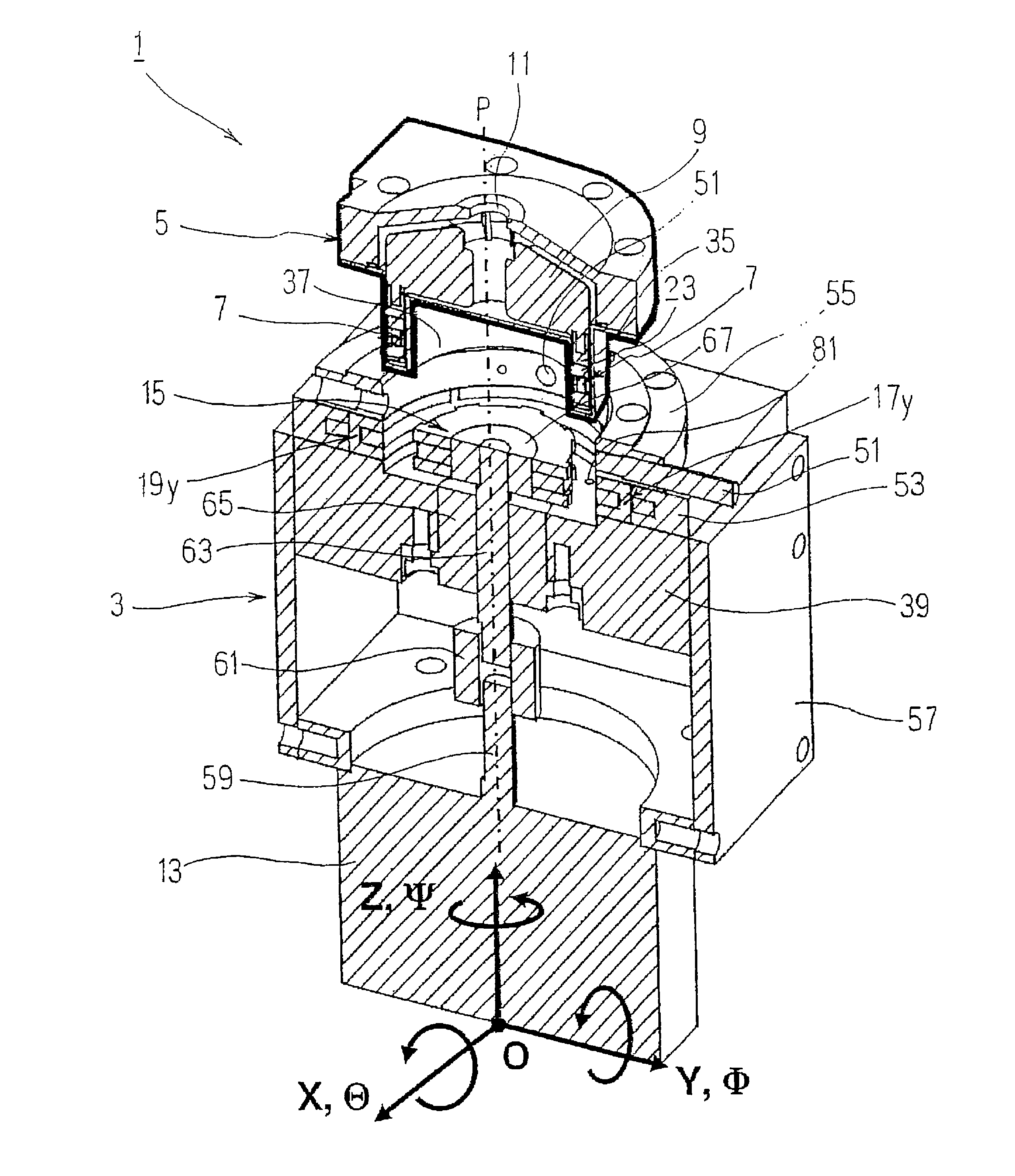
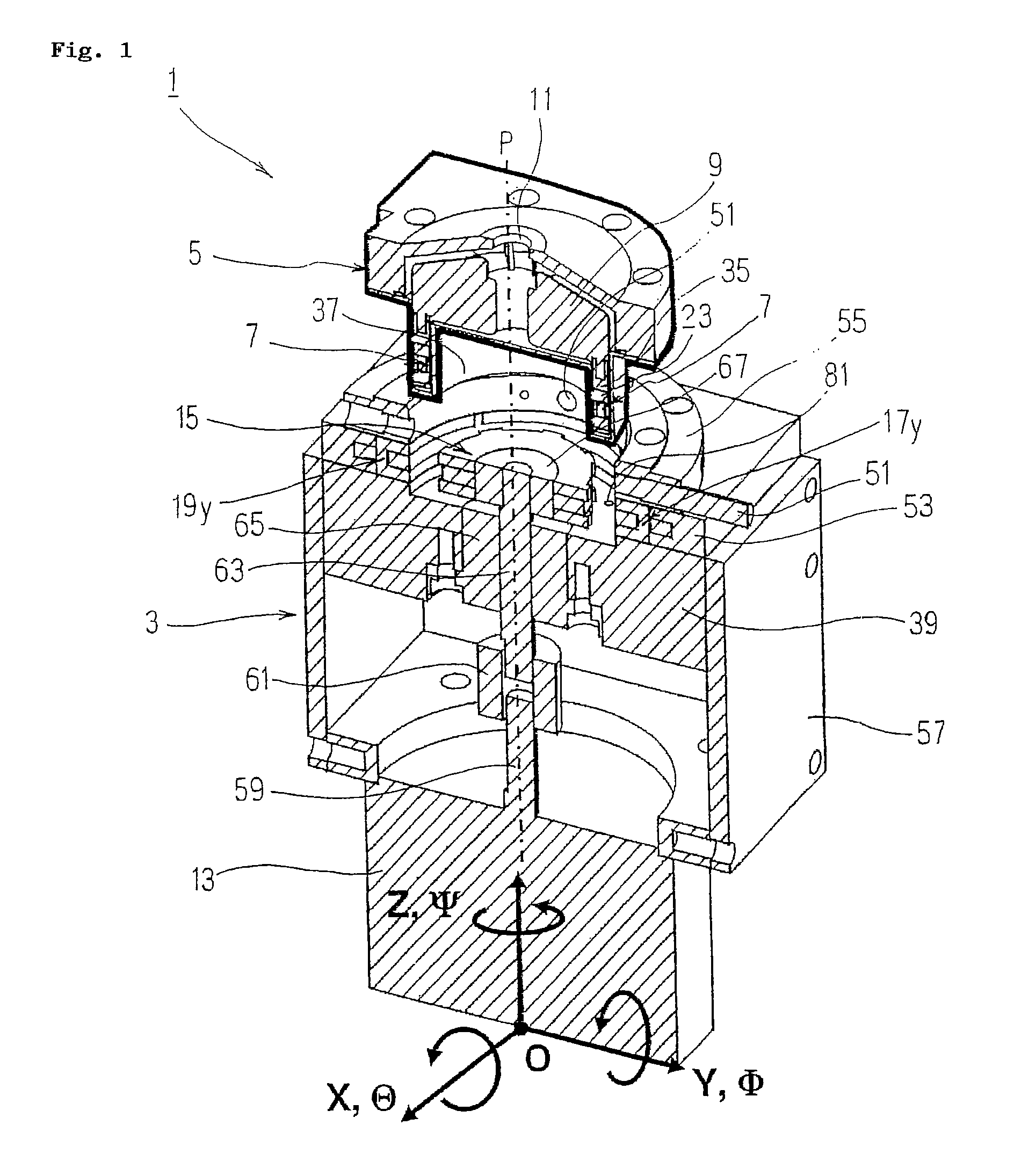
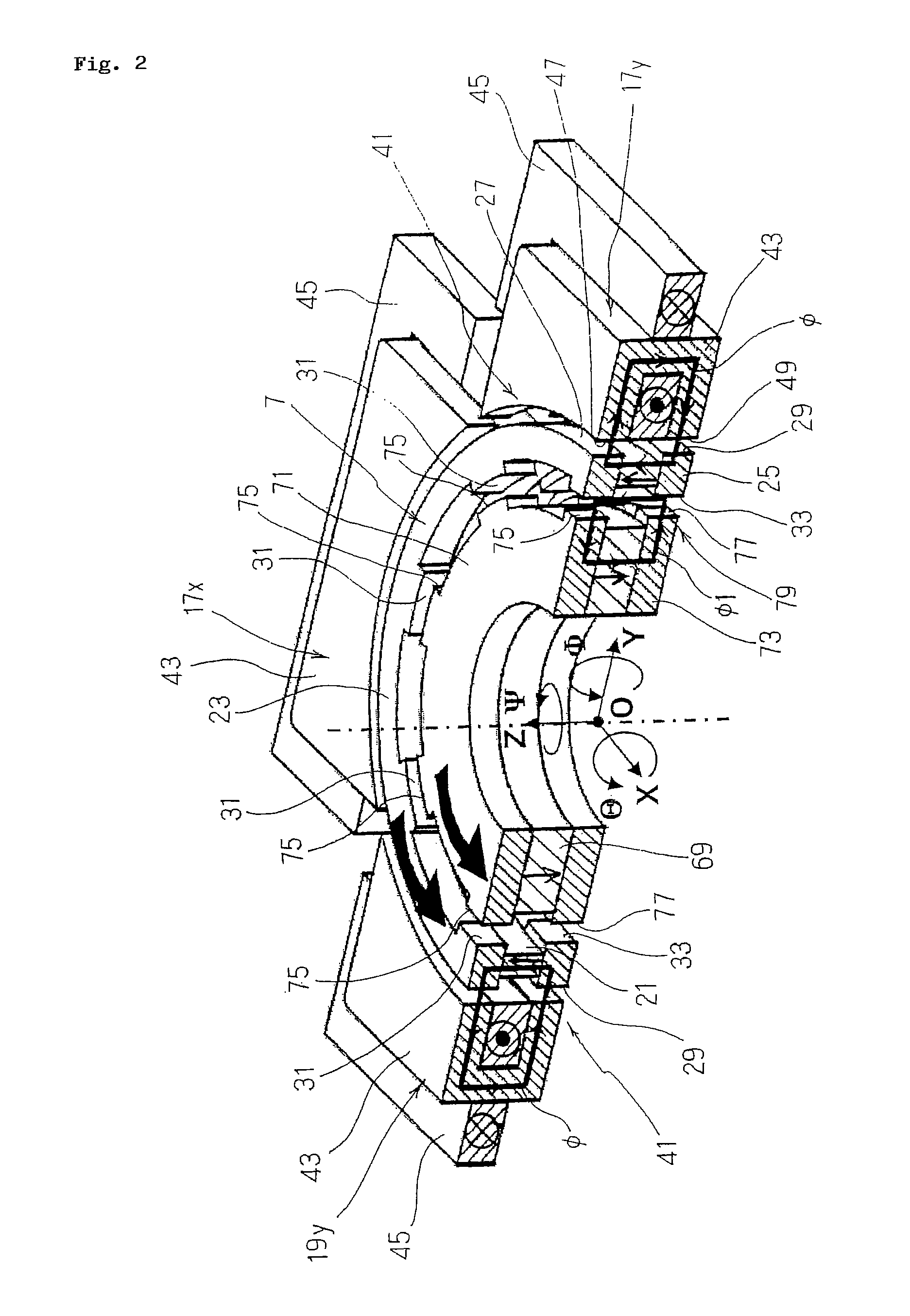
[0034]FIG. 1 to FIG. 6 illustrate a disposable centrifugal blood pump with magnetic coupling (hereinafter referred to as “centrifugal blood pump with magnetic coupling”) according to claim 1 to claim 3. As shown in FIG. 1, a centrifugal blood pump with magnetic coupling 1 according to this embodiment includes a stator 3 and a housing 5 which is detachably attached to the upper surface of the stator 3 and, as described below, a blood-contact part including the housing 5, a rotor 7, an impeller 9, and so on mounted to the interior thereof and being surrounded by a thick line in the drawing corresponds to a disposable part, and blood flowed from an inflow 11 on top of the housing 5 is provided with kinetic energy by the rotation of the impeller 9 and flowed out from an outflow (not shown) on a side surface thereof.
[0035]Then, the stator 3 including a brushless DC motor (hereinafter referred to as “motor”) 13 arranged apart from the housing 5, a torque transmission disk 15 rotating sync...
second embodiment
[0104]FIG. 9 shows the centrifugal blood pump with magnetic coupling according to claim 1 to claim 3, and in the embodiment shown in FIG. 1 to FIG. 6, the four electromagnets 17x, 19x, 17y, 19y are arranged around the rotor 7 (housing 5) at the intervals of 90°. However, three electromagnets 109, 111, 113 having the same structure as the electromagnet 17y may be arranged around the rotor 7 (housing 5) at regular intervals of 120° as shown in FIG. 9.
[0105]According to this embodiment, there are infinite numbers of combination as methods of power supply to the coils 45 of the respective electromagnets 109, 111, 113. As an example, by providing an electric current ix to the electromagnet 109 and providing an electric current −ix in the opposite direction to the electromagnet 111, a drive force only in the direction X is generated.
[0106]The configuration of other parts is the same as the embodiment shown in FIG. 1, and hence description thereof will be omitted.
[0107]In this manner, acco...
PUM
 Abstract
Description
Claims
Application Information
 - R&D
- Intellectual Property
- Life Sciences
- Materials
- Tech Scout
- Unparalleled Data Quality
- Higher Quality Content
- 60% Fewer Hallucinations
Browse by: Latest US Patents, China's latest patents, Technical Efficacy Thesaurus, Application Domain, Technology Topic, Popular Technical Reports.
© 2025 PatSnap. All rights reserved.Legal|Privacy policy|Modern Slavery Act Transparency Statement|Sitemap|About US| Contact US: help@patsnap.com


