Multiple layer conductor pin for electrical connector and method of manufacture

a technology of electrical connectors and conductor pins, applied in the direction of penetrating/cutting insulation/cable strands, coupling device connections, contact members, etc., can solve the problems of long-term reliability problems such as difficulty in over molding polymer insulation onto metal substrates, etc., to reduce or eliminate electrical stress and discharge effects, increase reliability in higher ac voltage connectors

Active Publication Date: 2012-02-28
TELEDYNE INSTR INC
View PDF100 Cites 18 Cited by
  • Summary
  • Abstract
  • Description
  • Claims
  • Application Information

AI Technical Summary

Benefits of technology

[0011]The conductive or semi-conductive layer placed between the current carrying conductor and the high voltage insulator and bonded void free or substantially void free to the insulator substantially reduces or eliminates electrical stress and discharge effects resulting from potential voids between the conductor and the conductor insulation, and increases reliability in higher AC voltage connectors.

Problems solved by technology

Partial discharge at higher AC voltages between conductor and insulator in typical connectors and penetrators is a long term reliability problem.
In both of these methods, it is not possible to completely eliminate the air void between conductor and insulator, and the air void is a source for partial discharge phenomenon.
There is also difficulty in over molding a polymer insulation onto a metal substrate and achieving a consistently bonded interface.
Typically, air voids are formed at the interface due to shrinkage of the polymer during processing and coefficient of thermal expansion differences between the materials.
Since air is a poor insulator when compared with typical high voltage insulations, the electrical potential (voltage) will over-stress these air voids.
The resulting damage and ozone will eventually lead to a dielectric failure of the insulation.

Method used


Image

  • Multiple layer conductor pin for electrical connector and method of manufacture
  • Multiple layer conductor pin for electrical connector and method of manufacture
  • Multiple layer conductor pin for electrical connector and method of manufacture

Examples


Embodiment Construction

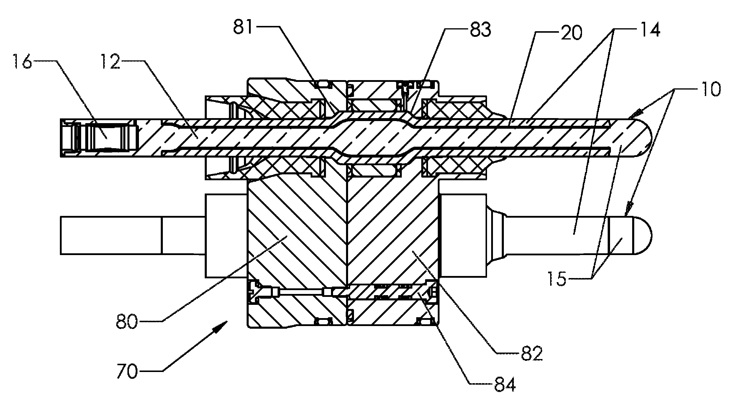
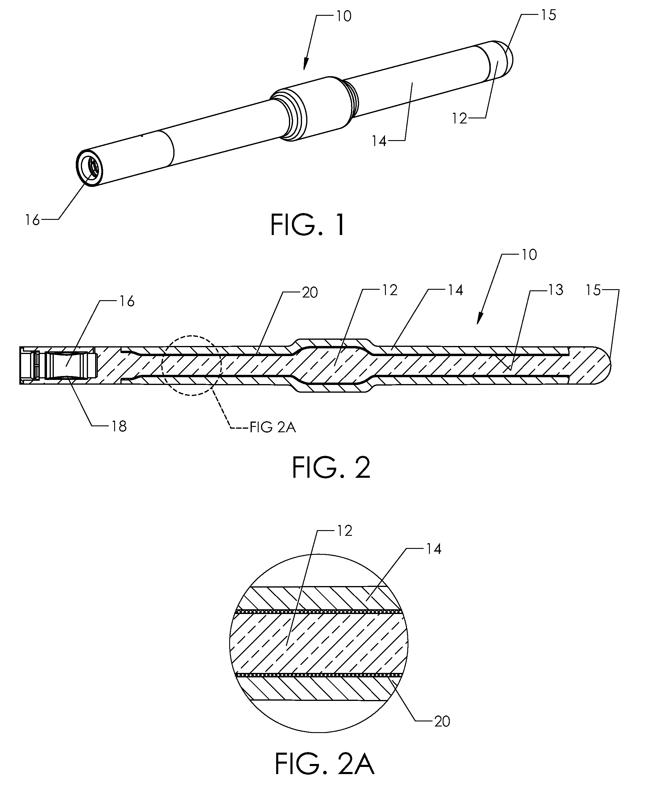
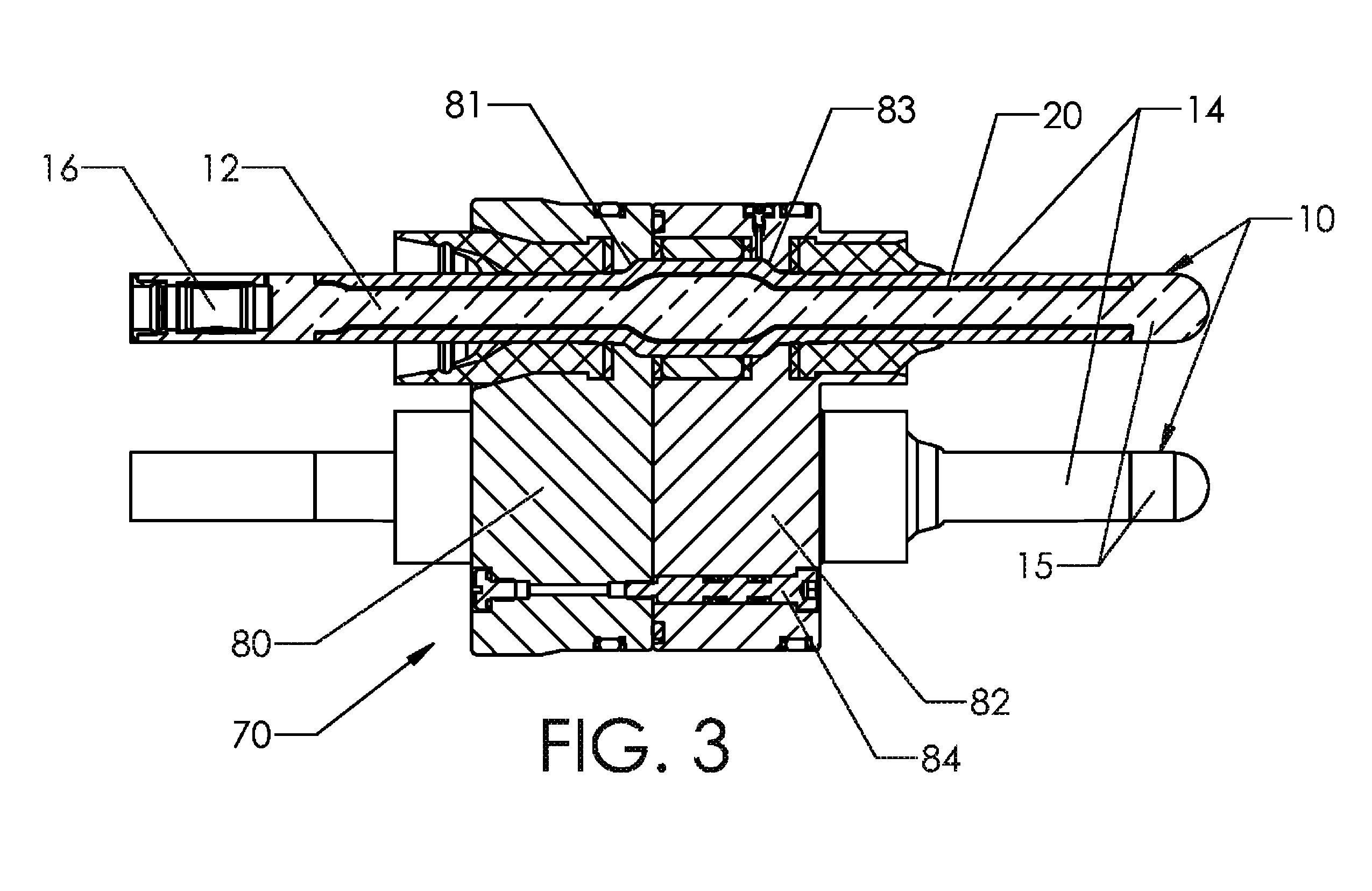
[0020]Certain embodiments as disclosed herein provide for a multiple layer conductor pin for an electrical connector or penetrator which may be designed for use underwater or in other harsh environments.

[0021]After reading this description it will become apparent to one skilled in the art how to implement the invention in various alternative embodiments and alternative applications. However, although various embodiments of the present invention will be described herein, it is understood that these embodiments are presented by way of example only, and not limitation. As such, this detailed description of various alternative embodiments should not be construed to limit the scope or breadth of the present invention.

[0022]FIGS. 1 to 2A illustrate a first embodiment of a conductive or semi-conductive layered conductor pin 10 suitable for incorporation in a plug unit of a releasably mateable electrical connector, such as the wet mate connector described in co-pending U.S. patent applicati...


PUM


Abstract

A multiple layer conductor pin for a harsh environment connector or penetrator has a conductive shaft, an outer layer of non-conductive, insulating material extending along at least part of the length of the shaft, and an intermediate layer of conductive or semi-conductive material sandwiched between the outer layer and conductive shaft and bonded substantially void-free to the outer insulating layer.

Description

RELATED APPLICATION[0001]The present application claims the benefit of co-pending U.S. provisional pat. App. Ser. No. 61 / 231,521, filed Aug. 5, 2009, the contents of which are incorporated herein by reference in their entirety.BACKGROUND[0002]1. Field of the Invention[0003]The present invention relates generally to electrical connector or penetrator assemblies for connecting two cables or connecting a cable to electrical equipment, and is particularly concerned with a multiple layer conductor pin for incorporation in electrical or hybrid connectors or penetrators for subsea use or use in other harsh environments, and a method of manufacturing the multiple layer pin.[0004]2. Related Art[0005]Electrical connector or penetrator units include one or more conductors or conductor pins which extend through the units to carry current between opposite ends of the connector or penetrator connecting two cables or a cable and electrical equipment. Typically such conductors are surrounded by an ...

Claims


Application Information

Patent Timeline
Patent Type & Authority Patents(United States)
IPC IPC(8): H01R4/24
CPCH02G3/22H01R13/187H02G9/02E21B33/0385
Inventor JAZOWSKI, ROYRAMASUBRAMANIAN, SRIKANTHHAWKINS, DANSIVIK, GREGORY
Owner TELEDYNE INSTR INC
Why Eureka
Try Eureka