Thick electrode direct reaction fuel cells utilizing cross-flows and taylor vortex flows

Active Publication Date: 2012-02-28
GLOBAL ENERGY SCI CALIFORNIA
View PDF8 Cites 46 Cited by
  • Summary
  • Abstract
  • Description
  • Claims
  • Application Information

AI Technical Summary

Benefits of technology

[0036]It is therefore an advantage of the present invention to provide an improvement over the robust direct reaction fuel cell (DRFC) of Case D by providing thick, densely catalytic porous electrodes.
[0037]A second advantage of this invention is to provide direct reaction fuel cells that have thicker porous electrodes than conventional fuel cells in order to incorporate greater total amounts of catalyst surface that increase volumetric electrode current density (Amperes/cm3) than are available in prior art electrodes.
[0038]A third advantage of this invention is to provide a fuel cell with cross-flow of fuel or oxidizer to provide a greater cross-sectional electrode current d

Problems solved by technology

In the case of NAFION polymer PEM, acidic electrolytes must be used and the operating temperature must not exceed 190° C. As a result, expensive catalysts (e.g., Platinum Group m

Method used


Image

  • Thick electrode direct reaction fuel cells utilizing cross-flows and taylor vortex flows
  • Thick electrode direct reaction fuel cells utilizing cross-flows and taylor vortex flows
  • Thick electrode direct reaction fuel cells utilizing cross-flows and taylor vortex flows

Examples


Embodiment Construction

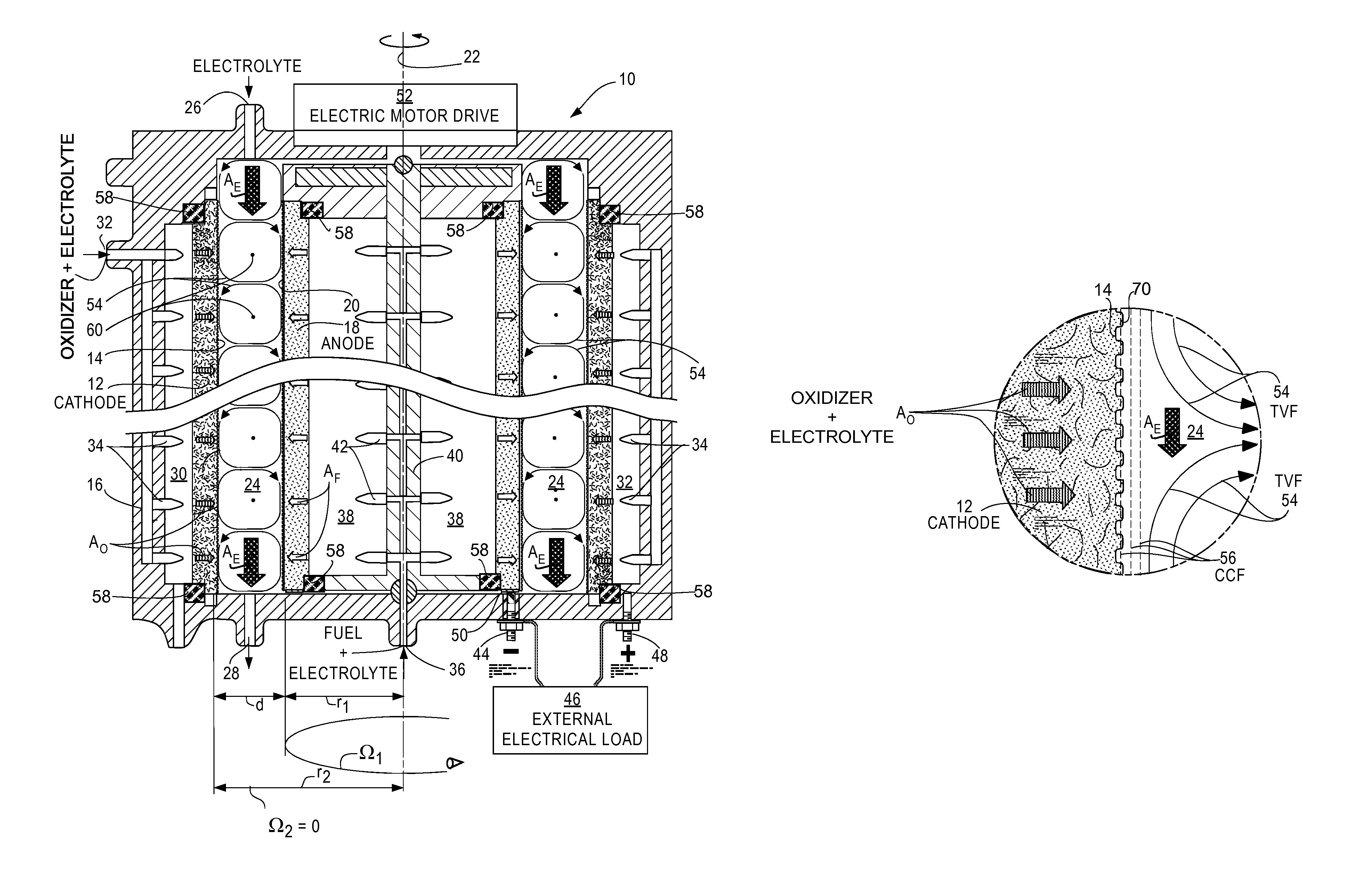
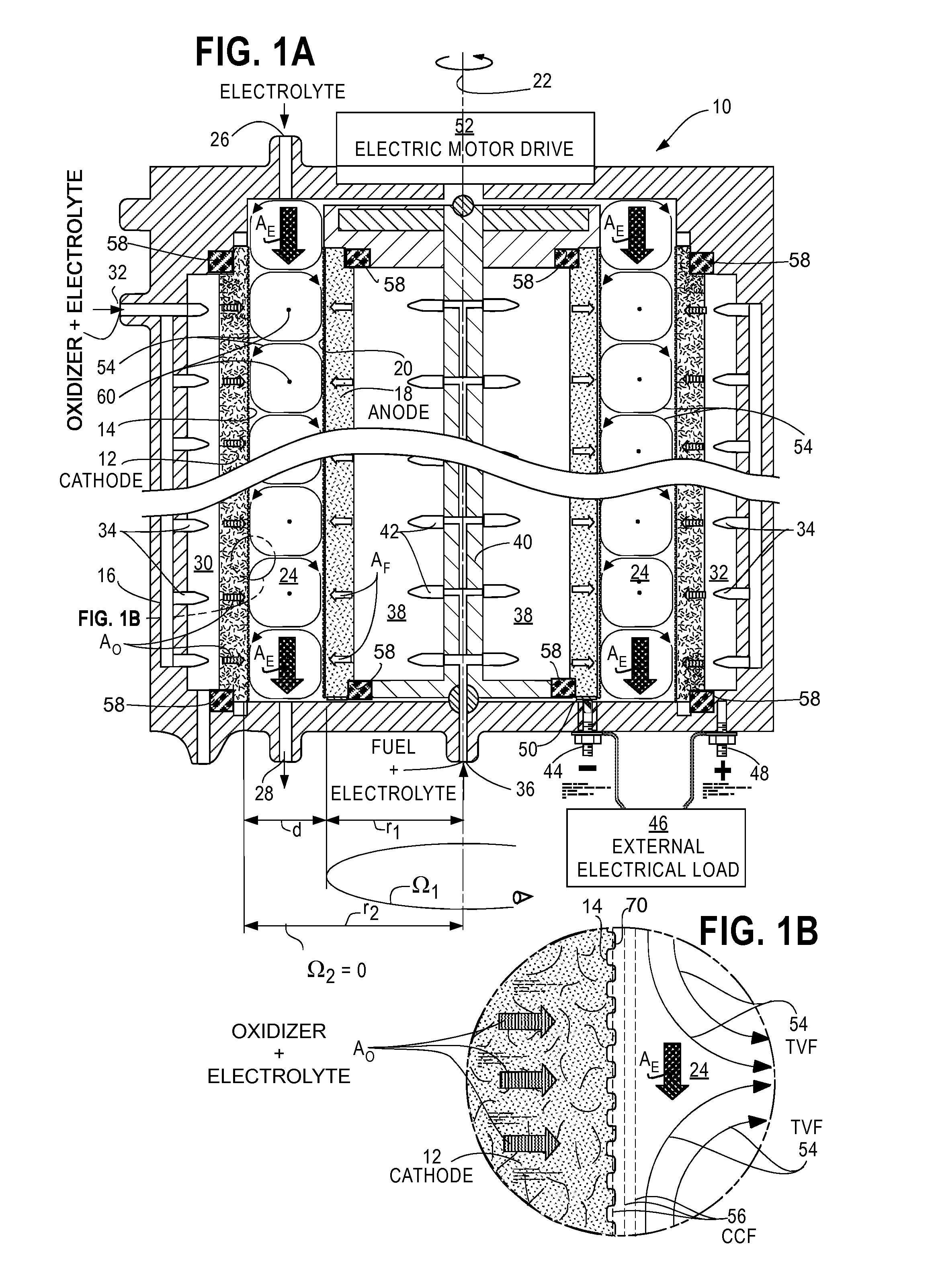
[0048]This TEDRFC invention is an improvement over my invention described in my Case D. The fuel cells of Case D eliminated any requirement for a PEM by using TVF to prevent fuel and oxidizer cross-over. Referring to FIG. 1A of Case D, which is a fragmentary view of a cross-sectional view of my DRFC, electrolyte is injected through electrolyte input tube 26 to electrolyte chamber 24 located between cathode electrode fixed cylinder 12 porous inner surface layer 14 and anode electrode rotating cylinder 18 porous outer surface layer 20. The electrolyte flows in an axial direction within the cylindrical fuel cell 10 as TVF 54 and leaves the electrolyte chamber 24 through electrolyte exit tube 26.

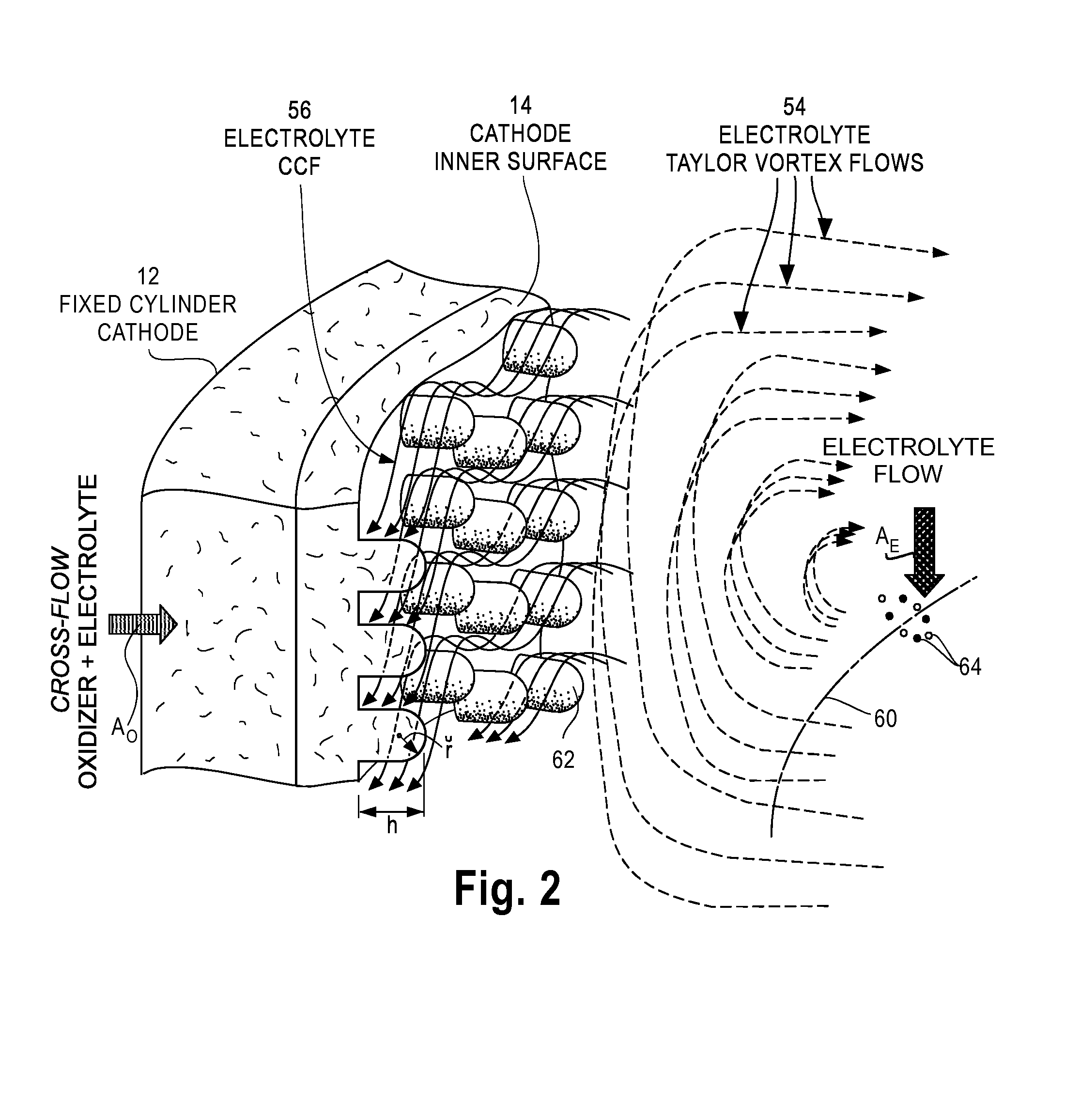
[0049]As shown in FIG. 1B of Case D, the TVF 54 generate CCF 56 that interact chemically with catalytic protuberances extending from a cathode porous inner catalytic surface layer 14 into the electrolyte chamber 24. The electrolyte does not penetrate to any appreciable depth into the cathode ele...


PUM


Abstract

Direct reaction fuel cells (10) with cross-flow of an electrolyte mixture through thick, porous electrodes (12, 18) that contain a mixture of catalyst particles and that rotate to generate Taylor Vortex Flows (54) and Circular Couette Flows (56) in electrolyte chambers (24) are disclosed.

Description

CROSS-REFERENCE TO RELATED APPLICATIONS[0001]This patent application claims the benefit of U.S. Provisional Patent Application No. 61 / 388,359 filed 30 Sep. 2010, and of International Patent Application No. PCT / US10 / 39885 filed 25 Jun. 2010, which is a continuation-in-part of U.S. patent application Ser. Nos. 12 / 800,658 (U.S. Pat. No. 8,017,261 of 13 Sep. 2011); 12 / 800,710; 12 / 800,657; 12 / 800,672 (U.S. Pat. No. 7,972,747 of 5 Jul. 2011); and 12 / 800,709 (U.S. Pat. No. 7,964,301 of 21 Jun. 2011)—all filed on 20 May 2010. All of these applications claim priority from U.S. Provisional Patent Application 61 / 220,583 filed 26 Jun. 2009, are hereby incorporated herein by reference in their entirety and have been assigned to the assignee of this application.[0002]This application, identified as Case G, is related to my following applications:[0003]Case A: Electrochemical Cells Utilizing Taylor Vortex Flows, application Ser. No. 12 / 800,658 of 20 May 2010, published as US 2010-0330439 A1 on 31 ...

Claims


Application Information

Patent Timeline
IPC IPC(8): H01M8/02H01M50/77
CPCH01M8/08H01M4/8626H01M8/04186H01M8/04276H01M8/04798Y02E60/50H01M8/22H01M8/225H01M4/8673H01M4/9016H01M4/9041H01M8/0438H01M8/04388H01M8/04395
Inventor FISCHEL, HALBERT
Owner GLOBAL ENERGY SCI CALIFORNIA
Why Eureka
Try Eureka