Preventing gas from occupying a spray nozzle used in a process of scoring a hot glass sheet

a technology of hot glass and spray nozzle, which is applied in the direction of glass tempering apparatus, separation process, liquid degasification, etc., can solve the problems of discontinuous crack propagation of glass sheet, laser scoring process failure, etc., and achieve enhanced spray nozzle performance.

Active Publication Date: 2012-03-13
CORNING INC
View PDF9 Cites 49 Cited by
  • Summary
  • Abstract
  • Description
  • Claims
  • Application Information

AI Technical Summary

Benefits of technology

[0017]The purge nozzle removes air bubbles from the water stream such that the water flow is not interrupted out of the tip of the nozzle assembly while it traverses the hot glass during quenching. This is accomplished by placing the purge opening in the top portion of the nozzle body in the area where the micro air bubbles coalesce and stagnate in the nozzle body and nozzle tip region. The purge opening is controlled with the purge line solenoid valve. When the purge line solenoid valve is open, air bubbles are redirected from the purge nozzle out of the purge line. The redirected flow evacuates the stagnated area from the nozzle body, sweeping out the troublesome air bubbles from this region and discarding them.
[0019]Once the purging nozzle is installed and the purging is operational, the nozzle tip operates normally (i.e., like at room temperature) even though the 400° C. glass ribbon is just inches away from the nozzle body. Due to the radiant heating of the nozzle body and nozzle tip from the glass ribbon, the uncooled nozzle assembly temperature is maintained at about 65° C. At this elevated temperature the air solubility is significantly reduced compared to room temperature, which reduces the water's ability to hold in solution the naturally dissolved air it contained at 25° C.
[0024]A fifth embodiment features a method for preventing gas from occupying a spray nozzle used in quenching a sheet of hot glass during a scoring process. Provided is a source of pressurized quenching liquid, a main liquid supply line leading from the pressurized quenching liquid source, a spray nozzle including a body having a nozzle passageway in communication with the main liquid supply line, and a tip connected to the nozzle body in communication with the nozzle passageway. The tip has an orifice adapted to release a jet of the quenching liquid. A gas removal device is used to remove gas from the quenching liquid, which prevents the gas from occupying the spray nozzle. A jet of the quenching liquid is sprayed through the orifice onto the sheet during a scoring process without interruption in the jet. Once the scoring process is complete, the jet of the quenching liquid is shut off without a substantial time delay.
[0027]Primary advantages of the gas removing features disclosed herein, the purge nozzle, purge nozzle with pre-staging of bubbles, cooling coil and gas filter, include the ability to use the spray nozzle in a solid or misting stream condition at elevated temperature without an interruption in water flow from the nozzle. Also, the spray nozzle can deliver a fluid in close proximity to a high temperature source without an interruption in flow. The spray nozzle can operate like at room temperature while spraying high temperature fluid. The features disclosed herein can be applied to removing various gases from various liquids at a range of temperatures. These features also prevent air bubbles from covering the nozzle orifice opening and causing an interruption or perturbation of water flow out of the spray nozzle. Furthermore, these features remove air bubbles from the nozzle tip such that shut off performance of the spray nozzle is enhanced.

Problems solved by technology

If the water jet sputters, even for a microsecond, during the quenching process the quenching of the glass sheet will be discontinuous.
This sporadic condition is unacceptable since when the water flow is stopped, quenching is stopped, and the crack that is propagated across the glass sheet is therefore also stopped.
This causes the laser scoring process to fail.
If an interruption in quench spraying occurs, local sheet cracks or entire ribbon cracking in the glass could occur due to unsuccessful separation.
If water dribbles out from the nozzle after the water flow from the nozzle is turned off, it might contact a quality region of the glass, resulting in potential weakening of the glass there and likely scrapping of that section of glass sheet.
It was discovered that due to this heating, the air solubility of the water in the nozzle and accompanying water supply tubing was changing, causing the dissolved air in the supply water to outgas and form air spaces or air bubbles in the tubing, nozzle body and nozzle tip.
These air bubbles accumulated, which in turn raised two issues.
First, if large enough, these air bubbles covered the nozzle orifice and caused an interruption in water flow out of the nozzle.
Second, the presence of air bubbles caused an undesirable delay in the time required to turn on or turn off the nozzle at the end of the scoring stroke.
This in turn undesirably caused the water stream to continue flowing and to strike the next glass sheet in the quality area as the system traversed back to its home position.
Then, when the water flow through the spray nozzle is turned off, the now compressed larger bubbles expand as the system returns to atmospheric pressure, which undesirably displaces water from the nozzle.
Meanwhile, the glass is broken by robotic bending of the glass sheet while holding the glass with suction cups.

Method used


Image

  • Preventing gas from occupying a spray nozzle used in a process of scoring a hot glass sheet
  • Preventing gas from occupying a spray nozzle used in a process of scoring a hot glass sheet
  • Preventing gas from occupying a spray nozzle used in a process of scoring a hot glass sheet

Examples


example

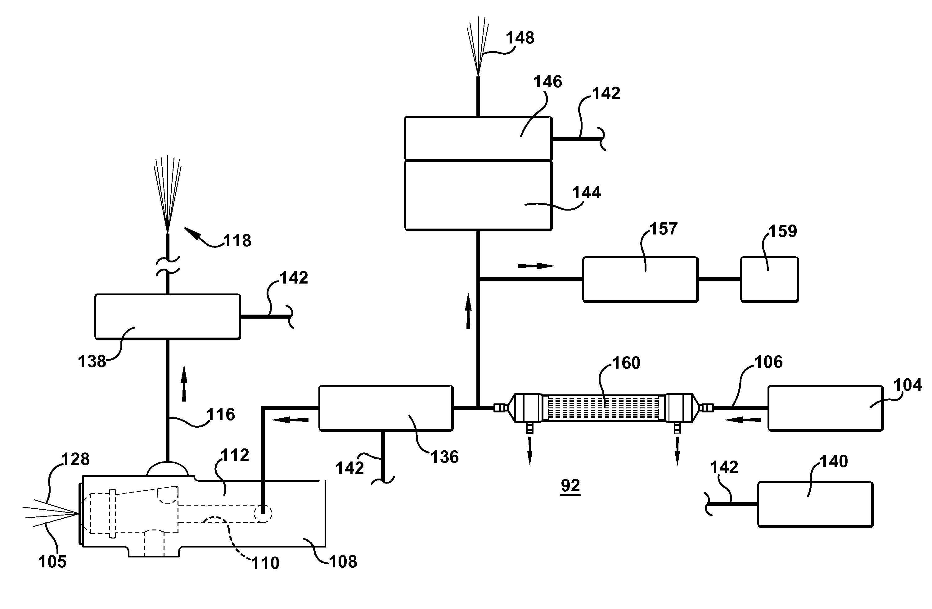
[0048]This example describes operation of the purge nozzle. The following is a pre-purging sequence. The pre-purging sequence is conducted only to remove gross air bubbles from the system such as when a nozzle tip is replaced or during system start up. First, the primary solenoid valve is turned off and the purge or secondary solenoid is turned off. The water pressure is on. The water supply pressure within the laser scoring environment ranges from about 3 to 70 psi. The pressure is provided by an air charged pressure pot. The pressure transducer reports pressure as a function of time in the water line. The air accumulator purge valve is closed. Next, the primary solenoid is turned on. The air accumulator valve is open for 5 seconds and then closed. The secondary solenoid is on for about 10 seconds at 10 hertz oscillation. This creates turbulent flow in the purge nozzle to disrupt bubbles located there. The secondary solenoid is then turned off. The primary solenoid is turned off. T...


PUM

PropertyMeasurementUnit
speedaaaaaaaaaa
temperatureaaaaaaaaaa

Abstract

A spray nozzle is used in a process of quenching a hot glass sheet during a laser scoring process or other high energy glass heating process. The scoring is conducted by a high energy means such as a laser. The nozzle is located in proximity to the glass sheet, creating gas in liquid used to quench the glass located in the nozzle (e.g., water). The gas (e.g., air bubbles) is removed from the quenching liquid. Then, the spray nozzle is used to spray the quenching liquid onto the sheet at a location trailing laser scoring of the sheet, such as using a traveling anvil machine at the bottom of the draw. The spray nozzle (purge nozzle) has a purge opening and tubing leading to a discharge location. The purge nozzle can have a sloped passageway that pre-stages gas bubbles near the purge opening in the nozzle. The spray nozzle can include a cooling coil passing around the nozzle passageway that enables a coolant to travel along the coil. This cools the quenching liquid passing through the nozzle, and increases the solubility of bubbles in the quenching liquid in the nozzle. A gas filter can receive gas-rich quenching liquid from the pressurized quenching liquid source, remove gas from the liquid, and send gas-depleted quenching liquid to the spray nozzle.

Description

BACKGROUND OF THE INVENTION[0001]1. Technical Field[0002]The field is quenching a sheet of hot glass during the scoring process with a jet of water.[0003]2. Technical Background[0004]A fusion process (e.g., downdraw process) forms high quality thin glass sheets that can be used in a variety of devices such as flat panel displays. Glass sheets produced in a fusion process have surfaces with superior flatness and smoothness when compared to glass sheets produced by other methods. The fusion process is described below with respect to FIG. 1 (Prior Art) but for a more detailed description refer to co-assigned U.S. Pat. Nos. 3,338,696 and 3,682,609, which are incorporated herein by reference in their entireties.[0005]FIG. 1 shows a schematic view of an exemplary glass manufacturing system 10 which utilizes the fusion process to make a glass sheet 12. As shown, the exemplary glass manufacturing system includes a melting vessel 14, a fining vessel 16, a mixing vessel 18, a delivery vessel ...

Claims


Application Information

Patent Timeline
Patent Type & Authority Patents(United States)
IPC IPC(8): C03B33/00C03B33/02C03B33/037C03B33/023
CPCC03B27/0404C03B33/091C03B21/02C03B33/023B01D19/0042C03B33/102C03B33/0222B01D19/0031C03B33/10C03B33/09
Inventor BROWN, JAMES WILLIAMGARGANO, PATRICK MICHAELHILL, KEITH MITCHELLLI, XINGHUARYSZYTIWSKYJ, WILLIAM PAULZHOU, NAIYUE
Owner CORNING INC
Why Eureka
Try Eureka