
RFID systems and methods for automatically detecting and/or directing the physical configuration of a complex system

a technology of radiofrequency identification and physical configuration, applied in the direction of electrical signalling details, burglar alarm mechanical actuation, instruments, etc., can solve the problems of delay in providing the most up-to-date information about the system configuration, labor-intensive and easy to error, and equipment is capabl

Active Publication Date: 2012-03-20
FIBER MOUNTAIN INC
View PDF44 Cites 214 Cited by
  • Summary
  • Abstract
  • Description
  • Claims
  • Application Information

AI Technical Summary

Benefits of technology

The patent describes a system for detecting, directing, and configuring a complex system made up of different components. The system uses RFID tags that are associated with each component and are designed to mate with other components in the system. The RFID tags have information about their associated component, and when two components mate, the RFID tags exchange information and communicate the configuration of the system. The system includes an RFID reader and an information processing system that receives and processes the RFID signals to determine the configuration of the system. The system can also be directed by an RFID tag to connect components in a specific way. The technical effects of this system include improved detection and configuration of complex systems, improved efficiency in assembly, and improved user experience.

Problems solved by technology

A common issue in telecommunications data center management is determining the current configuration of all the optical and electrical links among all the network hardware equipment.
Another issue is that some equipment is capable of being installed in any one of multiple orientations when only one particular orientation is correct or desirable.
This process is labor-intensive and prone to errors.
Additionally, any changes made to the physical configuration of any network equipment must be followed up with corresponding changes to the network management software database, which delays providing the most up-to-date information about the system configuration.
Furthermore, errors from manual recording and entry of configuration data tend to accumulate over time, reducing the trustworthiness of the network management software database.
In addition, the need to connect a given connector or install a given piece of equipment in only one of a number of possible orientations also leads to errors in the system's physical configuration, as mentioned above.
Finally, it is better to know of an incorrect connection as soon as it is made, rather than sometime later when a problem arises (e.g., loss of a connection or loss of data), and when the source of the problem is more difficult to diagnose.

Method used


Image

  • RFID systems and methods for automatically detecting and/or directing the physical configuration of a complex system
  • RFID systems and methods for automatically detecting and/or directing the physical configuration of a complex system
  • RFID systems and methods for automatically detecting and/or directing the physical configuration of a complex system

Examples


Embodiment Construction

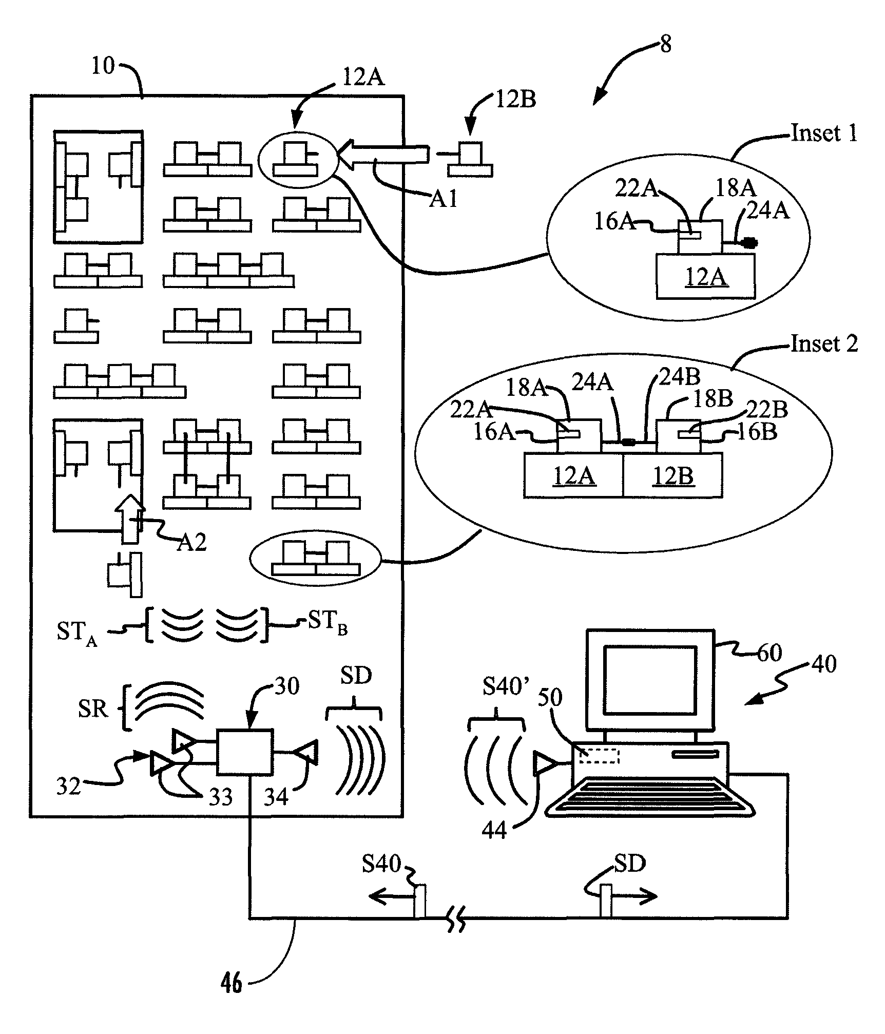
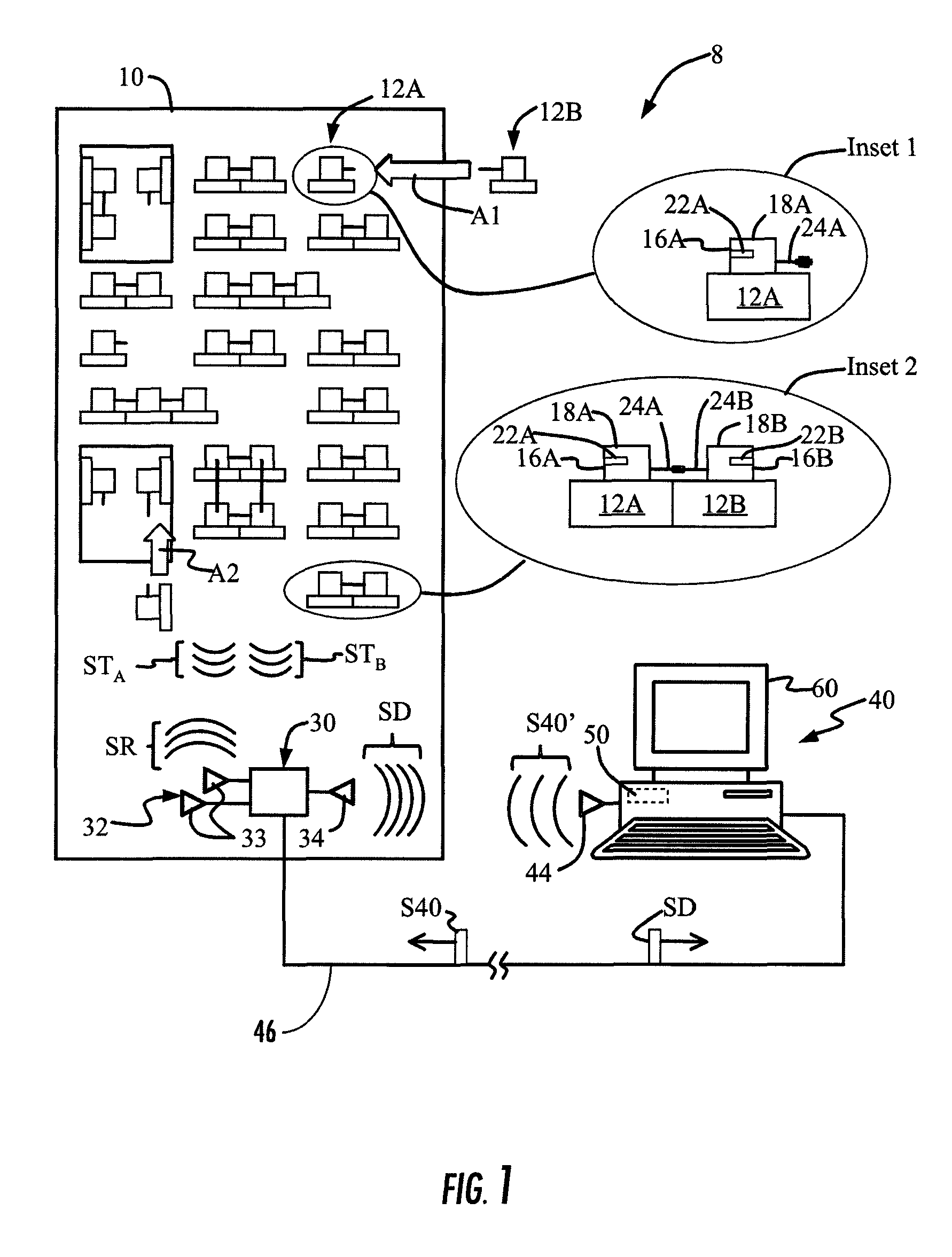
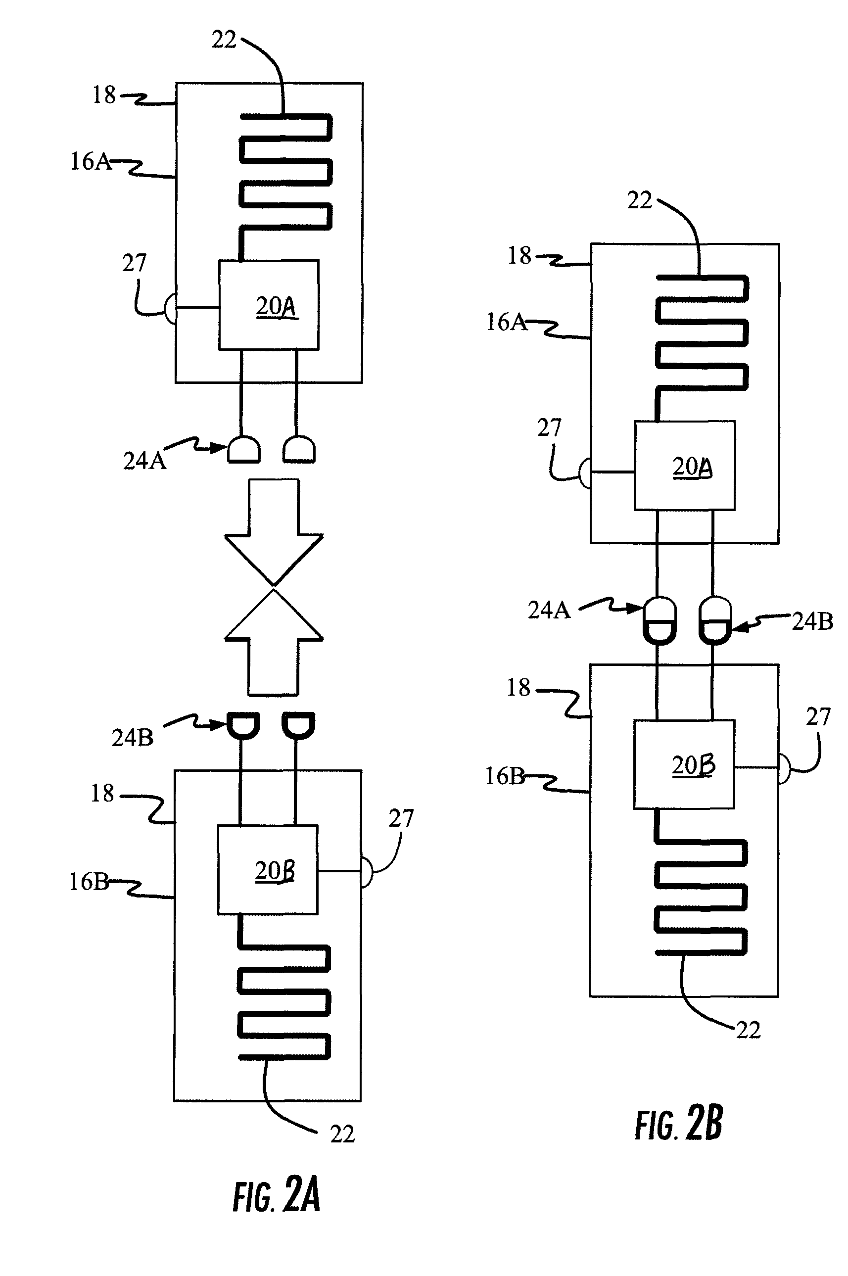
[0009]A first aspect disclosed in the detailed description is a radio-frequency identification (RFID) system for detecting, directing, and / or configuring a configuration of a complex system having a set of one or more types of mateable components. The system includes a set of mateable RFID tags arranged so that each mateable component in the set includes at least one mateable RFID tag. The mateable RFID tags include information relating to their associated mateable components and are arranged so that the mating of components results in the mating of the corresponding RFID tags. The RFID system includes at least one RFID reader adapted to read an RFID tag signal sent from at least one RFID tag in a mated pair of RFID tags, wherein the at least one RFID tag signal contains information about the mated components. The RFID system also includes an information processing system operably connected to the at least one RFID reader. The information processing system is adapted to receive and ...


PUM


Abstract

A radio-frequency identification (RFID)-based configuration detection system for automatically detecting, directing, and / or configuring the physical configuration of a complex system constituted by a set of one or more types of mateable components. The RFID configuration detection system utilizes a set of mateable RFID tags arranged so that each mateable component includes at least one mateable RFID tag. Each RFID tag includes information about its associated component and is arranged so that when the components are mated, their associated RFID tags also are mated. The system uses at least one RFID reader to read RFID tag signals from the RFID tags. The RFID tag signals provide information about mating status of the component, as well as information about components themselves. An information processing system operably connected to the RFID reader receives and process information concerning the number and type of mated connections and thus the configuration. Changes to the configuration, such as mated connections being unmated, can be tracked to provide real-time configuration information.

Description

RELATED APPLICATIONS[0001]The present application claims priority to U.S. Provisional Patent Application Ser. No. 61 / 011,194, filed on Jan. 15, 2008 and entitled “RFID SYSTEMS AND METHODS FOR AUTOMATICALLY DETECTING AND / OR DIRECTING THE PHYSICAL CONFIGURATION OF A COMPLEX SYSTEM,” which is incorporated herein by reference in its entirety.BACKGROUND[0002]1. Field of the Disclosure[0003]The technology of the disclosure relates generally to the use of radio-frequency identification (RFID) systems, and in particular is directed to RFID-based systems and methods for automatically detecting, directing, and / or configuring the physical configuration of a complex system, such as a telecommunications system.[0004]2. Technical Background[0005]Typical telecommunications data centers include large numbers of optical and electrical cable connections that join various types of network equipment. Examples of network equipment include electrically-powered (active) units such as servers, switches and...

Claims


Application Information

Patent Timeline
Patent Type & Authority Patents(United States)
IPC IPC(8): G08B13/14
CPCG06K5/02G06K17/0006G06K19/0723G06K19/0717H04Q1/149G06K2017/0093H05K7/1498
Inventor DOWNIE, JOHN DAVIDSUTHERLAND, JAMES SCOTTWAGNER, RICHARD EDWARDWHITING, MATTHEW SCOTTWEBB, DALE ALANHOOVER, KEITH ALLENCHAMARTI, ARAVIND
Owner FIBER MOUNTAIN INC
Learn More