System and method for locomotive exhaust gas recirculation cooling and catalyst heating

a technology of catalyst heating and exhaust gas recirculation, which is applied in the direction of machines/engines, mechanical equipment, non-fuel substance addition to fuel, etc., can solve the problems of high egr temperatures that may require significantly increased engine cooling system size and performance criteria, and require significant egr cooling. , to achieve the effect of reducing the required heat rejection of the engine coolant system, reducing the cooling requirements of the egr, and reducing the required cooling requirements

Active Publication Date: 2012-03-27
GE GLOBAL SOURCING LLC
View PDF12 Cites 4 Cited by
  • Summary
  • Abstract
  • Description
  • Claims
  • Application Information

AI Technical Summary

Benefits of technology

[0004]In one embodiment, at least some EGR is routed in a high pressure loop (e.g., from upstream of the turbine to downstream of the compressor). The EGR is thus at a higher pressure and temperature than exhaust gas or other exhaust components downstream of the turbine (due to the expansion through the turbine). As such, the higher pressure / temperature of the exhaust gas recirculation (relative to the exhaust gas or other exhaust components downstream of the turbine) thereby enables the heat transfer.
[0005]In this way, it is possible to cool the EGR and heat the exhaust downstream of the turbine, while at the same time reducing the required heat rejection to the engine coolant system. In other words, the rejected heat from the EGR system is advantageously used to heat other components in the exhaust that are below a desired operating temperature, rather than delivered to an already over-burdened cooling system. As such, emission control devices located downstream of the turbine can be maintained at higher temperatures, thereby improving emission control, while reducing cooling requirements of the EGR.

Problems solved by technology

However, several issues related to over temperature conditions and under temperature conditions can arise with such systems, especially in a locomotive context using diesel engines.
First, high EGR temperatures may require significant EGR cooling, such as where EGR heat is rejected to engine coolant.
However, the locomotive engine duty cycle may result in excessive heat rejection to the engine coolant from the EGR, thereby requiring significantly increased engine cooling system size and performance criteria.
Second, the expansion and associated temperature reduction of exhaust gasses through the turbine of a turbocharger can cause downstream emission control devices, such as catalytic converters, to cool below temperatures sufficient to perform a substantial amount of exhaust gas conversion (e.g. light-off temperatures).
The cooled conditions can result in reduced conversion efficiency, thereby increasing regulated emissions.

Method used


Image

  • System and method for locomotive exhaust gas recirculation cooling and catalyst heating
  • System and method for locomotive exhaust gas recirculation cooling and catalyst heating
  • System and method for locomotive exhaust gas recirculation cooling and catalyst heating

Examples


first embodiment

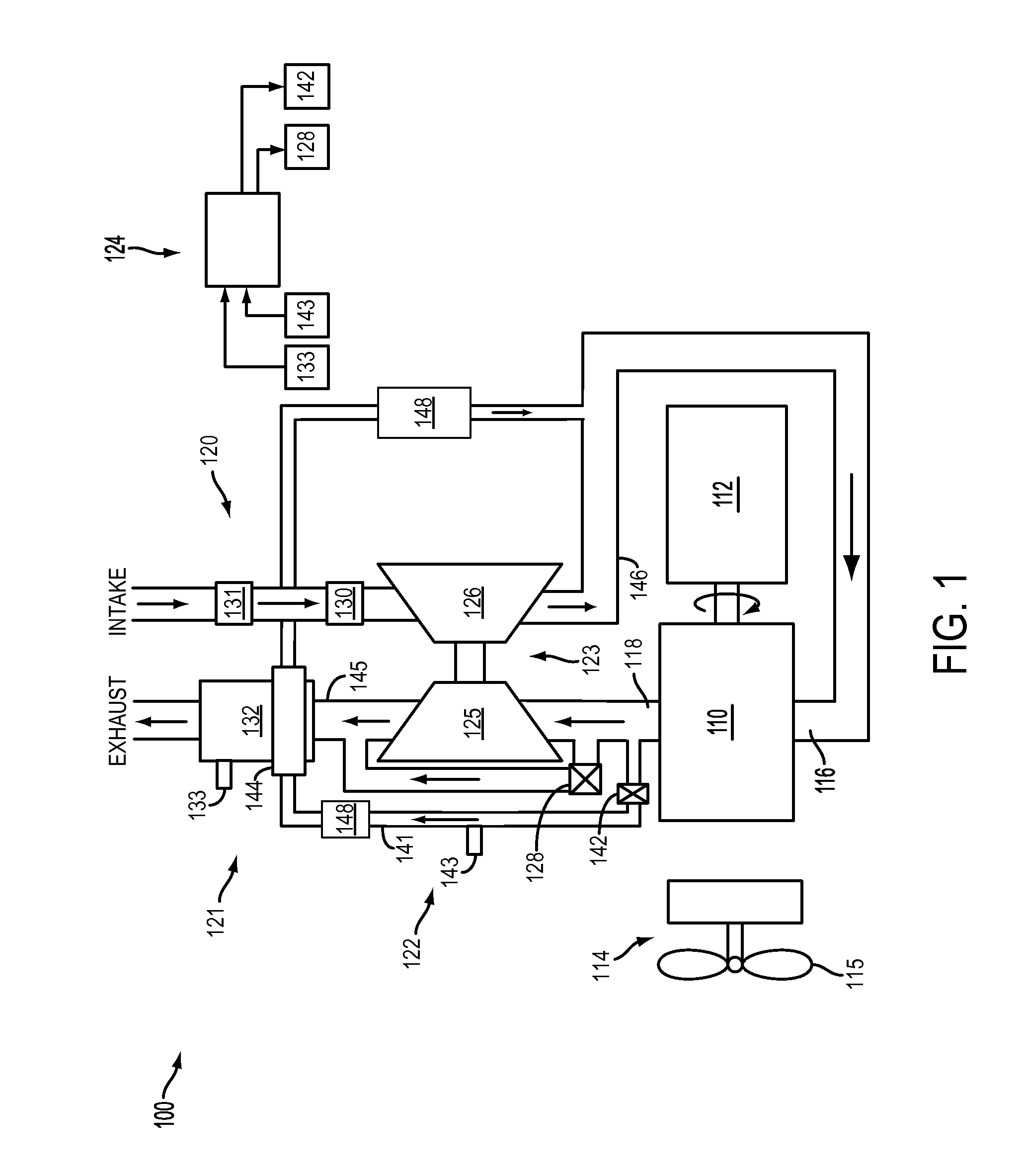
[0027]Referring now to FIG. 2, it shows an exhaust configuration with an air-to-air heat exchanger. In this configuration, heat exchanger 144 facilitates heat transfer from high pressure EGR to the emission control device 132 coupled to the exhaust downstream of the turbocharger turbine, thereby allowing the emission control device to operate above a threshold light-off temperature over a greater range of engine operating conditions.

[0028]In particular, FIG. 2 shows emission control device 132 coupled downstream of turbine 125. The emission control device includes a housing, or can, 212 enclosing bricks 214. Bricks 214 are configured to carry a catalyst washcoat on a support. The heat exchanger is coupled in the emission control device upstream of the bricks. The heat exchanger passively transfers heat from the high pressure EGR to exhaust gasses entering the emission control device at a position upstream of the bricks. In this way, heat can be transferred directly from the EGR to t...

second embodiment

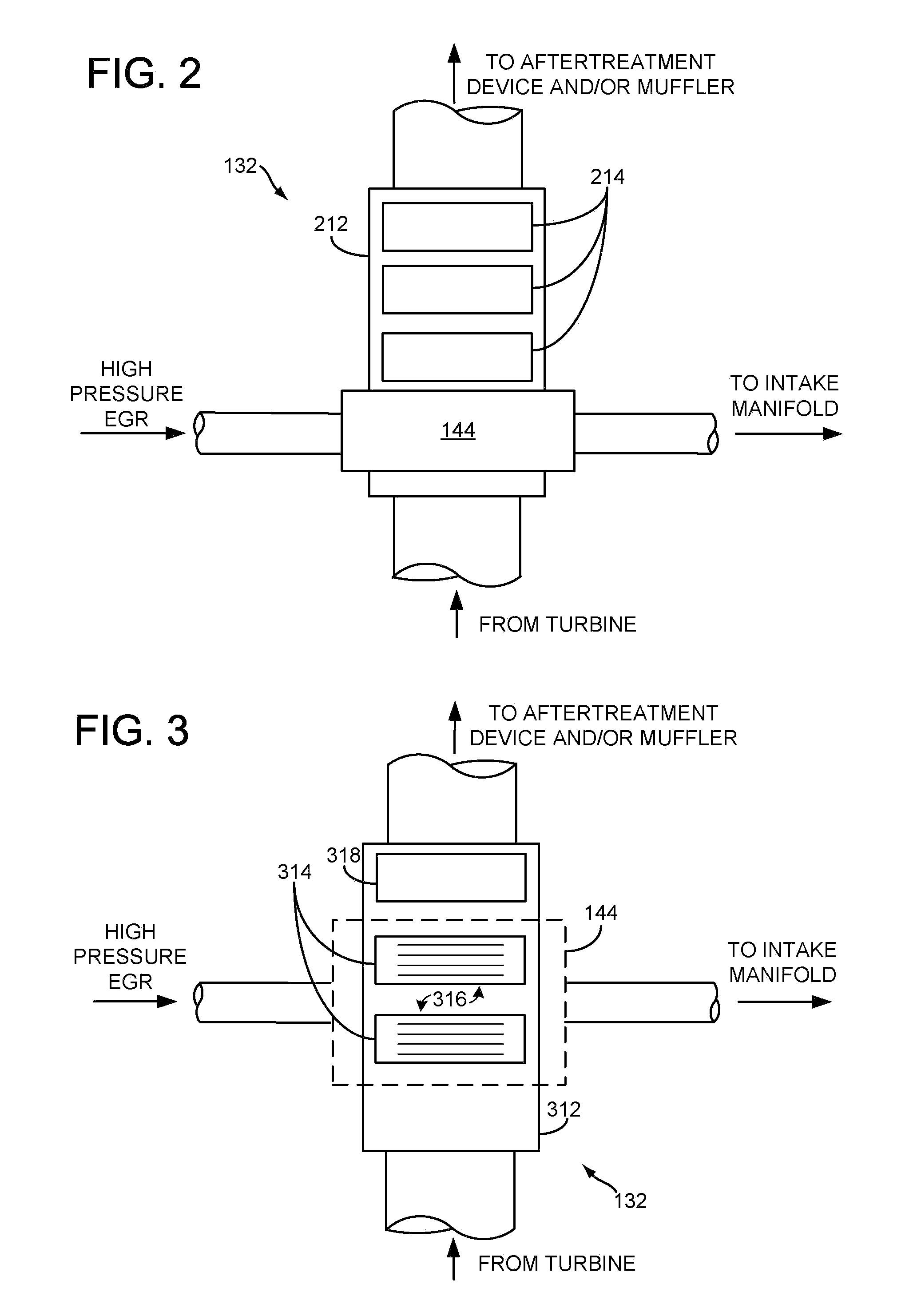
[0030]FIG. 3 shows an example configuration of the heat exchanger 144 and the emission control device 132. As shown, the emission control device includes a can 312 enclosing bricks 314. In this embodiment, the heat exchanger is coupled directly to a portion of the emission control device, and may be integrated into the emission control device. The heat exchanger may be configured to direct EGR flow over fins 316 coupled to the bricks and / or the can. Additional bricks may be coupled downstream of the heat exchanger, such as brick 318. As such, EGR heat is transferred to the emission control device.

[0031]FIGS. 4A-4E show various views of the third embodiment of an example configuration of heat exchanger 144 and emission control device 132. In the third embodiment, the heat exchanger is integrated into the emission control device allowing for a compact and efficient design. Specifically, in this embodiment, EGR flow is directed directly over and / or around the exterior of the catalyst b...


PUM


Abstract

A method of operating an internal combustion engine having an intake, an exhaust, and a turbocharger including a turbine and a compressor, the compressor coupled to the intake and the turbine coupled to the exhaust, the engine further having an exhaust gas recirculation system coupled to the exhaust upstream of the turbine and coupled to the intake downstream of the compressor, the method including transferring heat via a heat exchanger from the exhaust gas recirculation system to downstream of the turbine.

Description

BACKGROUND[0001]Engines may utilize recirculation of exhaust gas from the engine exhaust system to the engine intake system, a process referred to as Exhaust Gas Recirculation (EGR), to reduce regulated emissions and / or improve fuel economy. Additionally, engines may utilize turbochargers to increase power density and improve efficiency.[0002]However, several issues related to over temperature conditions and under temperature conditions can arise with such systems, especially in a locomotive context using diesel engines. First, high EGR temperatures may require significant EGR cooling, such as where EGR heat is rejected to engine coolant. However, the locomotive engine duty cycle may result in excessive heat rejection to the engine coolant from the EGR, thereby requiring significantly increased engine cooling system size and performance criteria. Second, the expansion and associated temperature reduction of exhaust gasses through the turbine of a turbocharger can cause downstream em...

Claims


Application Information

Patent Timeline
Patent Type & Authority Patents(United States)
IPC IPC(8): F02B33/44
CPCF01N5/02F02M25/0707F02M25/0718F02M25/073F02M25/0731F02M25/0732F01N3/2006F02B37/00F02B37/18F02M25/0754Y02T10/121Y02T10/16Y02T10/26F02M26/05F02M26/15F02M26/27F02M26/28F02M26/24F02M26/47Y02T10/12
Inventor YAGER, JAMES HENRY
Owner GE GLOBAL SOURCING LLC
Why Eureka
Try Eureka