Wave-motion reducing structure

Inactive Publication Date: 2012-03-27
OFFICINE MACCAFERRI SPA
View PDF17 Cites 0 Cited by
  • Summary
  • Abstract
  • Description
  • Claims
  • Application Information

AI Technical Summary

Benefits of technology

[0007]One of the main advantages of the present invention is that of reducing the energy of the wave motion without damaging the original structure of the sea bed, in particular, by damping transverse and lateral currents and preventing the raising of the waterline or “set up” line level, thus preventing erosion and modific

Problems solved by technology

As is known, erosion in progress on coastlines often requires the implementation of measures to prevent such processes.
Moreover, known structures cause so-called “rip” currents or “undertows”, particularly in the direction away from the land towards

Method used


Image

  • Wave-motion reducing structure
  • Wave-motion reducing structure
  • Wave-motion reducing structure

Examples


Embodiment Construction

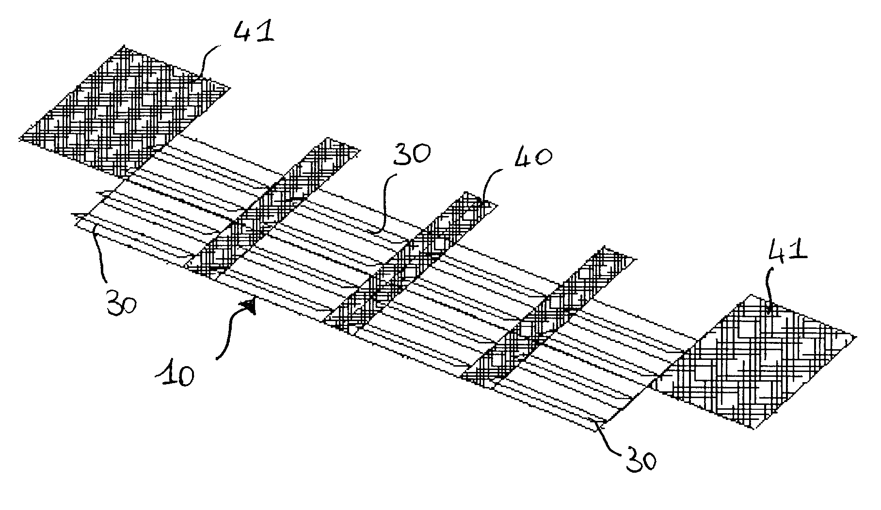
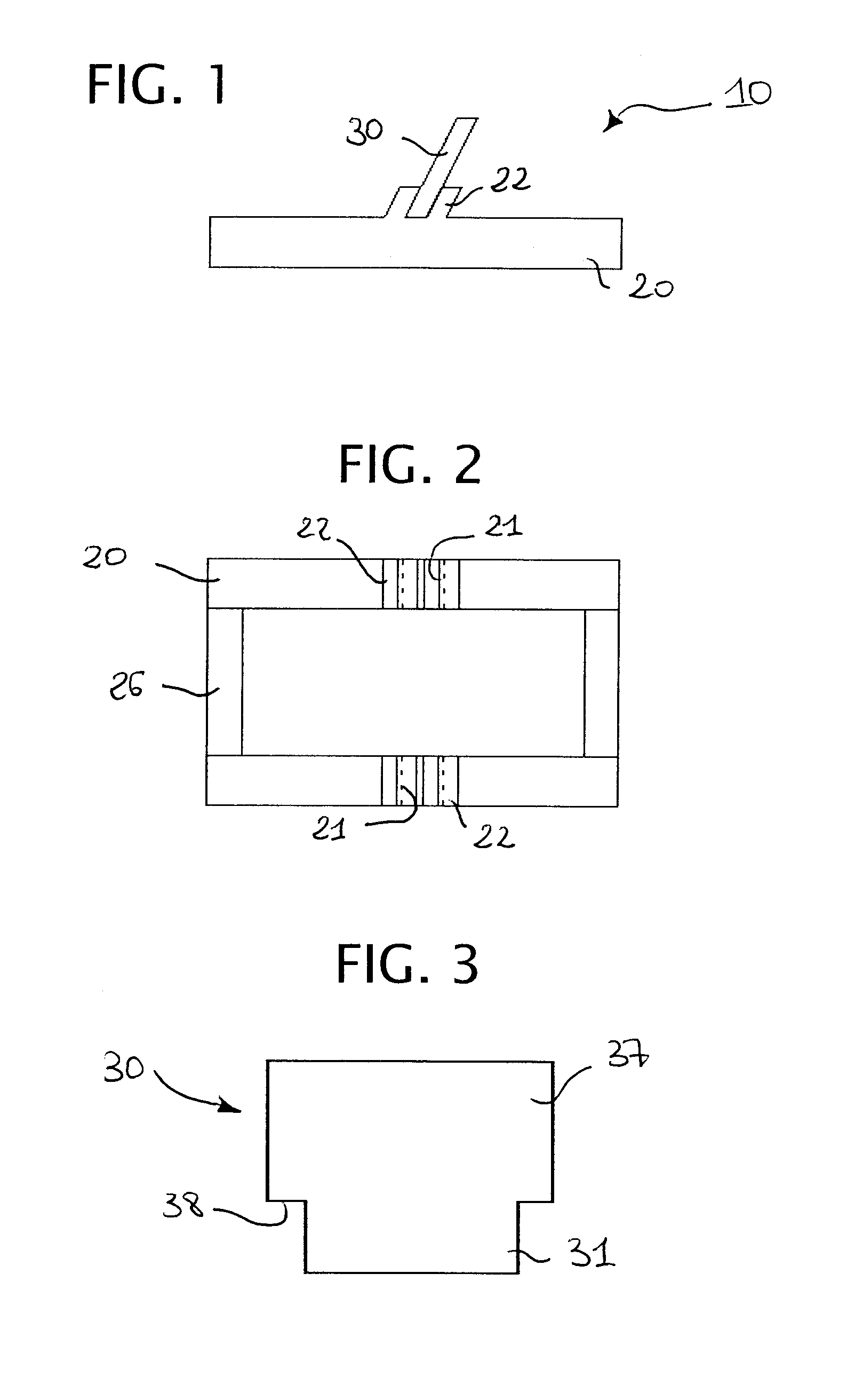
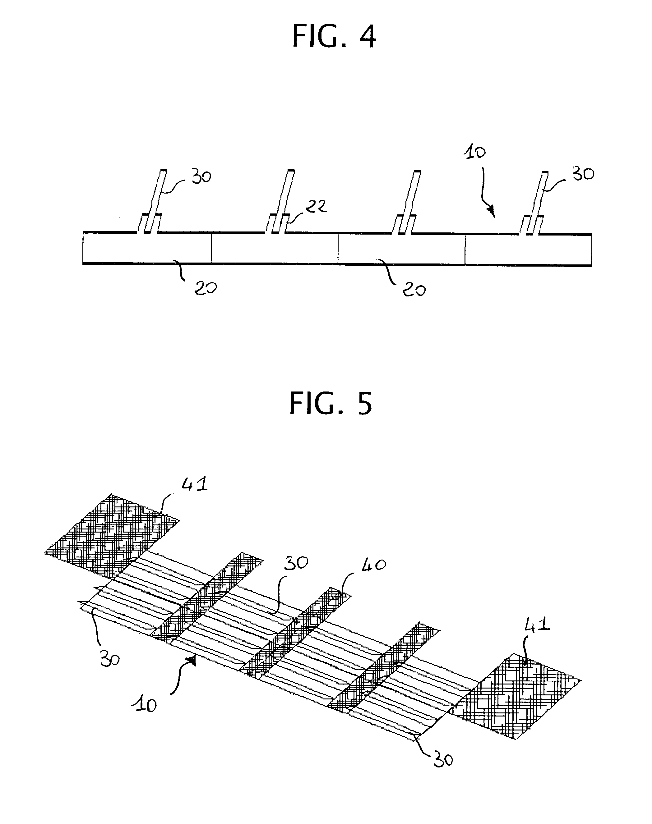
[0014]With reference now to the drawings, a wave-motion reducing structure, generally indicated 10, comprises wave-motion reducing means, for example, but in non-limiting manner, at least one panel 30, and restraining means which are particularly suitable for restraining the wave-motion reducing means on a coastal bed in use.

[0015]According to a preferred embodiment of the present invention shown in FIGS. 1 to 3, the restraining means comprise a base suitable for being laid on or fixed to a coastal bed. The base comprises a pair of longitudinal elements 20, for example, of elongate parallelepipedal shape, arranged parallel to one another and interconnected by transverse elements 26 so as to form a structure of overall rectangular shape in plan. Each longitudinal element 20 comprises, on its upper surface, two parallel projecting walls 22 which are inclined to the vertical, defining a seat 21. The seat 21 is particularly suitable for housing the panel 30 in use so as to restrain it o...


PUM


Abstract

A wave-motion reducing structure comprises wave-motion reducing means (30) suitable for being laid on a coastal bed and restraining means (20, 22) suitable for restraining the wave-motion reducing means on the coastal bed. The wave-motion reducing means (30) are arranged so as to be inclined, in use, against the direction of the sea current which strikes them. A wave-motion reducing system comprises a plurality of wave-motion reducing structures arranged in a row lengthwise and in a manner such that the wave-motion reducing means (30) adopt a substantially parallel configuration and oppose the motion of the current.

Description

BACKGROUND OF THE INVENTION[0001]The present invention relates to the field of wave-motion reducing structures and, more particularly, to a wave-motion reducing structure and to a wave-motion reducing system comprising the structure.[0002]As is known, erosion in progress on coastlines often requires the implementation of measures to prevent such processes. Known structures that are used for resisting erosion, such as breakwaters or groynes, may on the one hand bring advantages in the beach front region but, on the other hand, give rise to erosion processes at the bases of the structures, in the lateral areas, and in the spaces between the structures. Moreover, known structures cause so-called “rip” currents or “undertows”, particularly in the direction away from the land towards the open sea, which are damaging to coasts. Another disadvantage of these structures is therefore the need for constant maintenance and refilling works which are expensive and impose a burden on the funds of...

Claims


Application Information

Patent Timeline
IPC IPC(8): E02B3/04
CPCE02B3/06Y02A10/11E02B3/12
Inventor FERRAIOLO, FRANCESCO
Owner OFFICINE MACCAFERRI SPA
Why Eureka
Try Eureka