Micro fluidic system for single molecule imaging

a fluidic system and single molecule technology, applied in the field of manipulating molecules, can solve the problems of difficult landmarking techniques, reducing the possibility of preserving the molecule for later additional or more complex analysis, and complicating the process

Inactive Publication Date: 2012-03-27
WISCONSIN ALUMNI RES FOUND
View PDF30 Cites 2 Cited by
  • Summary
  • Abstract
  • Description
  • Claims
  • Application Information

AI Technical Summary

Benefits of technology

[0011]The present invention provides a method for straightening and fixing polymeric molecules using well-controlled laminar flow in a micro-channel. The laminar flow within a micro-channel allows sufficient diffusion of the ends of the molecule so that they may attach themselves to the wall of the micro-channel to be adsorbed and fixed in their straightened configuration.

Problems solved by technology

While these latter techniques potentially provide the same benefits of preserving the order and relative separation of the landmarks, motion of the molecule complicates the process of imaging the molecule, makes some landmarking techniques difficult, and eliminates the possibility of preserving the molecule for later additional or more complex analysis.
Points of overlap create image artifacts that can severely hamper the analysis process.
Inadequate elongation of the molecule, however, can make it difficult to identify the points cut by the restriction enzymes, which desirably separate slightly under relaxation of the elongated molecule to render the cuts visible.
Prior art techniques for elongating and fixing long chain molecules can produce excessive overlap among molecules and variation in molecule elongation.

Method used


Image

  • Micro fluidic system for single molecule imaging
  • Micro fluidic system for single molecule imaging

Examples


Embodiment Construction

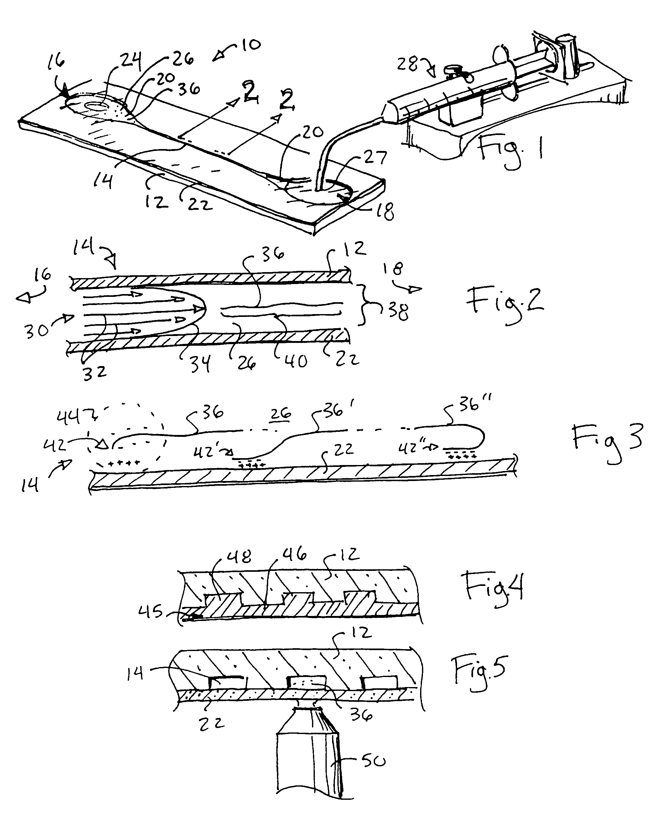
[0044]Referring now to FIG. 1, the apparatus 10 of the present invention provides a generally planar channel plate 12 into which a longitudinally extending micro-channel 14 is formed, flanked by a staging reservoir 16 and a collecting reservoir 18 positioned at longitudinal ends of the channel plate 12.

[0045]Junctions between the longitudinal ends of the micro-channel 14 and staging reservoir 16 and collecting reservoir 18 are tapered to create funnel sections with narrow ends attached to the micro-channel 14 and wide ends attached to one of the staging reservoir 16 or collecting reservoir 18. The funnel sections 20 provide a smooth transition of fluid from the staging reservoir 16 through the micro-channel 14 to the collecting reservoir 18 thereby promoting laminar flow within the micro-channel 14 and reducing breakage of polymeric molecules as will be described.

[0046]One common wall of the staging reservoir 16, the collecting reservoir 18, and the micro-channel 14 is provided by a...


PUM

PropertyMeasurementUnit
velocityaaaaaaaaaa
widthaaaaaaaaaa
widthaaaaaaaaaa

Abstract

Laminar flow of a carrier liquid and polymeric molecules through micro-channels is used to straighten the polymeric molecules and attach the straightened molecules to a wall of the micro-channel for subsequent treatment and analysis. Micro-channels can be manufactured using an elastic molding material. One micro-channel embodiment provides fluid flow using a standard laboratory centrifuge.

Description

CROSS-REFERENCE TO RELATED APPLICATIONS[0001]This application, which has been converted into a nonprovisional patent application from U.S. provisional patent application No. 60 / 419,884 filed Oct. 18, 2002, is a continuation-in-part of U.S. patent application Ser. No. 09 / 962,802 filed Sep. 24, 2001, now U.S. Pat. No. 6,610,256, which is a continuation of U.S. patent application Ser. No. 08 / 855,410 filed May 13, 1997, now U.S. Pat. No. 6,294,136, which is a continuation of U.S. patent application Ser. No. 08 / 415,710 filed Apr. 3, 1995, now U.S. Pat. No. 5,720,928.STATEMENT REGARDING FEDERALLY SPONSORED RESEARCH OR DEVELOPMENT[0002]This invention was made with United States government support awarded by the following agencies: DOE DE-FGO2-99ER62830 and NIH HG00225.[0003]The United States has certain rights in this invention.BACKGROUND OF THE INVENTION[0004]The present invention relates to methods of manipulating molecules and, in particular, to a fluid transport system useful for strai...

Claims


Application Information

Patent Timeline
Patent Type & Authority Patents(United States)
IPC IPC(8): G01N1/10
CPCG01N1/40G01N1/30Y10T436/25G01N1/405
Inventor SCHWARTZ, DAVID C.DIMALANTA, EILEEN T.DE PABLO, JUAN J.
Owner WISCONSIN ALUMNI RES FOUND
Why Eureka
Try Eureka