Manufacturing technology and device for improved forged steel roller neck high nickel chrome molybdenum alloy cast composite roller

A composite roll, high nickel-chromium technology, applied in the field of metal pressure processing, can solve the problems of rapid decline in hardness and wear resistance, poor thermal fatigue resistance, large hardness drop, etc., and achieve good red hardness and high temperature wear resistance. Good mechanical properties, the effect of reducing casting defects

Active Publication Date: 2016-03-16
丹阳恒庆复合材料科技有限公司
View PDF5 Cites 19 Cited by
  • Summary
  • Abstract
  • Description
  • Claims
  • Application Information

AI Technical Summary

Problems solved by technology

Therefore, when the core material is cast steel, a good composite interface cannot be obtained.
[0012] 3) Composite rolls with forged steel cores with high strength and high toughness cannot be produced
At present, it is mainly manufactured by the centrifugal composite casting process in China. Due to the limitation of the manufacturing process, the core is made of nodular cast iron. Due to the low strength of nodular cast iron, it is easy to break the roll during steel rolling production, which seriously affects the steel rolling production and product quality.
[0023] At present, centrifugal bainite rolls are usually used in the rolling of finished bars, slitting racks, and strips. This roll has the following shortcomings in the long-term use process: 1. The hardness drop is large, and the centrifugal bainite rolls From one use to the last use, the material structure changes greatly, the hardness and wear resistance decrease rapidly, and the rolling tonnage can decrease by 50-70 tons; 2. The thermal fatigue resistance is poor, and the rolls work at high temperature for a long time. Due to the thermal fatigue resistance of the roll, after a period of use, the roll is prone to cracks and surface blocks, which seriously affects the quality of the rolled piece; 3. The centrifugal bainite roll has low toughness and high brittleness, and roll breakage occurs from time to time
Moreover, because the graphite is in the form of flat strips and the carbides are in the form of a network, the matrix strength is relatively low. Therefore, in actual use, its wear resistance is still insufficient, and the service life is not long (the rolling amount of mm is generally 2000~ 3000 tons); secondly, due to the network structure of carbides and the boundary effect of graphite voids, the thermal crack resistance of the material is also poor, and the rolled rolls produced during the strip rolling process, with the rolling The increase of the amount will cause thermal cracks, so it is necessary to stop frequently to replace the roll, remove it for repair
It not only affects the shift production efficiency of the rolling mill, increases the intensity of replacement operations, and the workload of repairs; but also affects the surface quality of the rolled strip, and the repair of thermal cracks also reduces the service life of the rolls, resulting in higher production costs
The above problems lead to the short service life of centrifugal bainite rolls, which cannot meet the production requirements of high-efficiency rolling mills

Method used


Image

  • Manufacturing technology and device for improved forged steel roller neck high nickel chrome molybdenum alloy cast composite roller
  • Manufacturing technology and device for improved forged steel roller neck high nickel chrome molybdenum alloy cast composite roller
  • Manufacturing technology and device for improved forged steel roller neck high nickel chrome molybdenum alloy cast composite roller

Examples


Embodiment 1

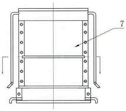
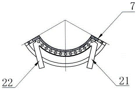
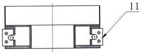
[0067] Embodiment 1: in figure 1 , figure 2 , image 3 , Figure 4 , Figure 5 , Figure 6 Among them, the equipment has a gantry-type regional directional solidification lifting device 16, a lifting platform 17 is installed on the gantry-type regional directional solidification lifting device 6, an electromagnetic induction heater 8 is installed on the lifting platform 17, and the lifting motor 14 rotates and lifts The screw 15 or hydraulic equipment drives the lifting table 17 to move up and down at the set speed, and the electromagnetic induction power control cabinet 19 is installed on the side of the directional solidification lifting equipment 16 in the gantry type area. The two output ends of the electromagnetic induction power control cabinet 19 are cooled by water. The cable 20 is connected to the two ends of the electromagnetic induction heater 8, and there is a base bracket at the bottom of the directional solidification lifting device 16 in the gantry type ar...

Embodiment 2

[0087] Example 2: In figure 1 , figure 2 , image 3 , Figure 4 , Figure 5 , Figure 6 Among them, the equipment has a gantry-type regional directional solidification lifting device 16, a lifting platform 17 is installed on the gantry-type regional directional solidification lifting device 6, an electromagnetic induction heater 8 is installed on the lifting platform 17, and the lifting motor 14 rotates and lifts The screw 15 or hydraulic equipment drives the lifting table 17 to move up and down at the set speed, and the electromagnetic induction power control cabinet 19 is installed on the side of the directional solidification lifting equipment 16 in the gantry type area. The two output ends of the electromagnetic induction power control cabinet 19 are cooled by water. The cable 20 is connected to the two ends of the electromagnetic induction heater 8, and there is a base bracket at the bottom of the directional solidification lifting device 16 in the gantry type area,...

Embodiment 3

[0106] Example 3: In figure 1 , figure 2 , image 3 , Figure 4 , Figure 5Among them, the equipment has a gantry-type regional directional solidification lifting device 16, a lifting platform 17 is installed on the gantry-type regional directional solidification lifting device 6, an electromagnetic induction heater 8 is installed on the lifting platform 17, and the lifting motor 14 rotates and lifts The screw 15 or hydraulic equipment drives the lifting table 17 to move up and down at the set speed, and the electromagnetic induction power control cabinet 19 is installed on the side of the directional solidification lifting equipment 16 in the gantry type area. The two output ends of the electromagnetic induction power control cabinet 19 are cooled by water. The cable 20 is connected to the two ends of the electromagnetic induction heater 8, and there is a base bracket at the bottom of the directional solidification lifting device 16 in the gantry type area, and a support...


PUM

PropertyMeasurementUnit
thicknessaaaaaaaaaa
tensile strengthaaaaaaaaaa

Abstract

The invention discloses a manufacturing technology and device for an improved forged steel roller neck high nickel chrome molybdenum alloy cast composite roller. The roller comprises, by mass percent, 3.0%-3.6% of C, 0.60%-1.20% of Si, 0.30%-1.20% of Mn, 3.0%-5.0% of Ni, 1.0%-2.0% of Cr, 0.40%-1.2% of Mo, 0.1%-2% of W, 0.5%-1.0% of Cu, not larger than 0.05% of P, not larger than 0.03% of S, 0.04%-0.06% of Mg, 0.1%-0.3% of Nb, 0.1%-0.30% of Ti, 0.2%-0.6% of V, 0.05%-0.2% of B, 1.5%-2.5% of Ba, 1%-2% of Ca, 1%-3% of Sb, 0.02%-0.18% of N, 1.0%-2.0% of Y/RE and the balance Fe and inevitable micro elements. Yttrium base rare-earth nodulizing and Ba, Ca, and silicon iron composite inoculation are adopted, Nb, Ti, V, B and Sb are added for modification, and the mechanical performance of the roller is improved; by the adoption of the forged steel roller neck, the strength of the roller is improved, an induction heater is adopted to carry out in-mold whole heating casting on a core stick, a water cooled crystallizer is molded, a composite layer interface can be dynamically controlled, the technology is simple, the efficiency is high, power consumption is small, the cost is low, no composition segregation exists, and the service life of the roller is long.

Description

technical field [0001] The invention belongs to the technical field of metal pressure processing, and in particular relates to a process and equipment for an improved forged steel roll neck high-nickel-chromium-molybdenum alloy cast iron composite roll, which is suitable for manufacturing composite rolls in the steel rolling industry. Background technique [0002] The roll is known as the "mother of steel". It is a tool for plastically deforming metal materials in the rolling production of steel, aluminum, copper and other metals. Rolling is an indispensable key component and the most important bulk consumption component, and its consumption cost is about 5% to 15% of the steel rolling production cost. If factors such as production downtime, reduced production and increased equipment maintenance due to roll consumption are considered, the proportion of production costs will be even higher. [0003] Rolling mill is an important equipment in metal pressure processing and prod...

Claims


Application Information

Patent Timeline
Patent Type & Authority Applications(China)
IPC IPC(8): C22C37/10C22C37/08B22D19/16B22D27/04C22C33/08C21D5/00C21D9/38
CPCB22D19/16B22D27/04C21D5/00C21D9/38C22C33/08C22C37/08C22C37/10Y02P10/20
Inventor 丁家伟丁刚耿德英鹿微微鹿策施孟达孔军
Owner 丹阳恒庆复合材料科技有限公司
Why Eureka
Try Eureka