Portable lubricant filtration system and method

a lubricant and filtration system technology, applied in the direction of filtration separation, multi-stage water/sewage treatment, separation process, etc., can solve the problems of premature wear and component or system failure, premature wear or even failure of machine elements, and lubricants may not meet the required target cleanliness code, so as to remove both particulate and fluid contamination from lubricants efficiently and economically

Active Publication Date: 2012-04-03
TRICO CORP
View PDF300 Cites 10 Cited by
  • Summary
  • Abstract
  • Description
  • Claims
  • Application Information

AI Technical Summary

Benefits of technology

[0007]The present invention is directed to a portable lubricant filtration system that is compact, self-contained, and able to remove both particulate and fluid contamination from lubricants efficiently and economically. The device may be utilized to filter lubricants in existing systems or may be used to pre-filter fluids during transfer between containers or systems, and is readily able to service multiple pieces of equipment.
[0008]Actively filtering lubricants from storage drums can prevent contamination related problems. The present system can prevent contamination or remove it when used in daily operations, including filtering lubricant directly from a storage drum to fill totes and transfer containers. The present system may supplement filtration systems and provides an inlet and outlet for continuous flow and metering of lubricants. The present system may also include inlet and outlet sampling ports for monitoring system efficacy and condition of the lubricant. The present system is capable of delivering a flow up to 4 GPM and is rated for use with lubricants up to a viscosity of 7,500 SUS, depending on motor selection. The present portable system is adapted for use with a FRL filter to remove moisture and debris from the air line and is further provided with a plurality of spin-on filter elements. Alternatively, the present system may be capable of delivering a flow up to 14 GPM when rated for use with lubricants up to a viscosity of 2,000 SUS, depending on motor selection. When pneumatic system is utilized, removal of moisture and debris from the air line is accomplished using a plurality of spin-on filter elements. Differential pressure gauges help specify the filter element condition and the need for replacement. The present invention ensures that equipment receives the cleanest lubricant possible, for increased equipment life, and therefore provides a plurality of filter elements for increased holding capacity.
[0012]Multiple filter elements—ability to utilize multiple filter elements for increased holding capacity and to remove water contamination.
[0019]Perceived advantages of the present invention include increased lubrication life; possibility to run at higher speeds; reduction in required oil level; maintain bearing life while consuming less oil; portability.

Problems solved by technology

Improper lubrication is likely to lead to premature component wear and component or system failure.
Although most lubricators provide reasonable performance in many steady-state operations, multiple variables can create unacceptable operating conditions and lead to premature wear, or even failure, of machine elements.
Unfortunately, “new” lubricants may not meet the required target cleanliness code and therefore should be filtered prior to being put into service.
Presently, there are very few devices adapted to filter lubricants having viscosities greater than 500 SUS @ 100° F. A problem with filtering a high viscosity lubricant with a lower viscosity system is that the pump and filters are not designed to work with the higher pressures required to push high viscosity fluids through the system.

Method used


Image

  • Portable lubricant filtration system and method
  • Portable lubricant filtration system and method
  • Portable lubricant filtration system and method

Examples


Embodiment Construction

[0026]Although the disclosure hereof is detailed and exact to enable those skilled in the art to practice the invention, the physical embodiments herein disclosed merely exemplify the invention which may be embodied in other specific structures. While the preferred embodiment has been described, the details may be changed without departing from the invention, which is defined by the claims.

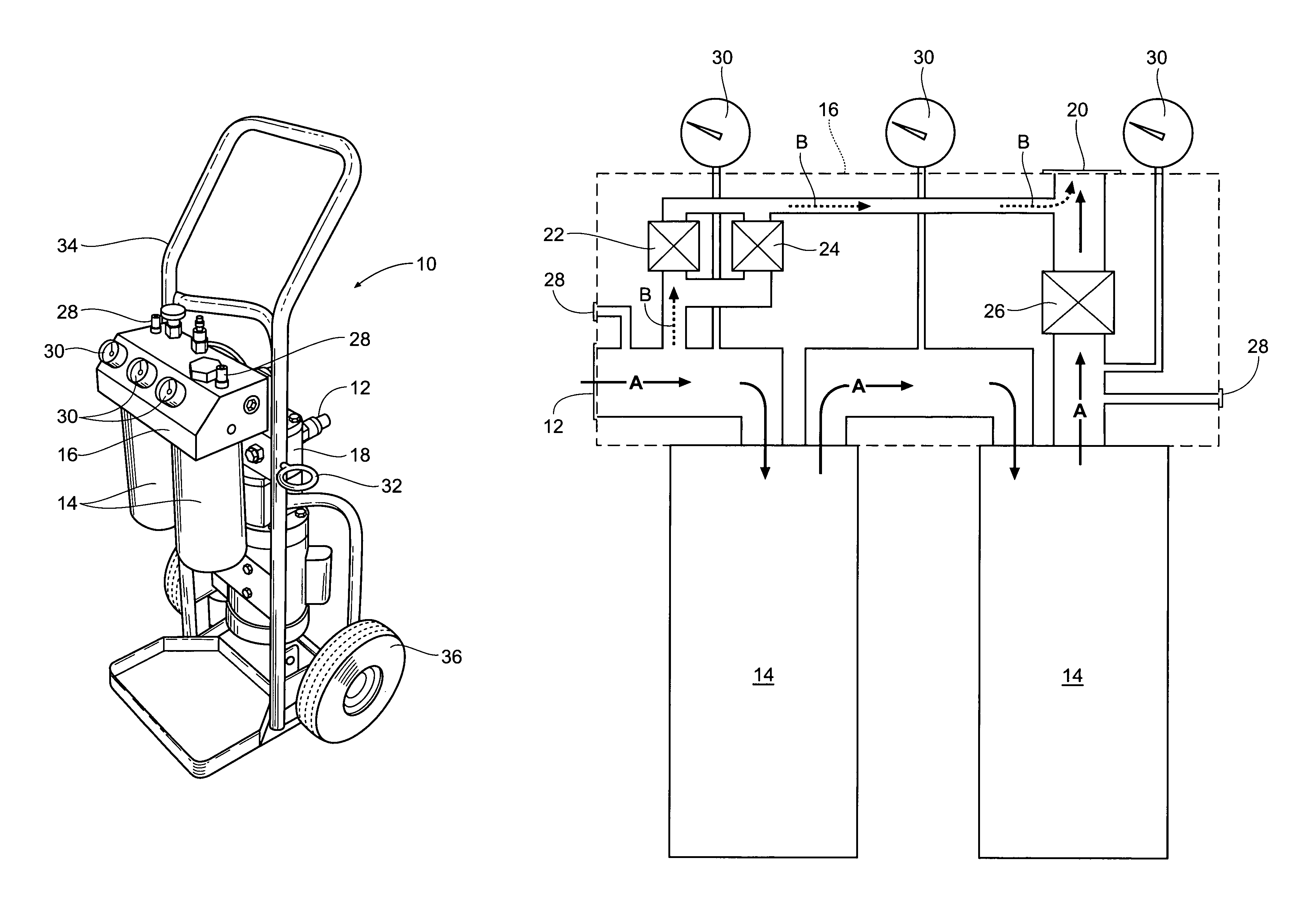
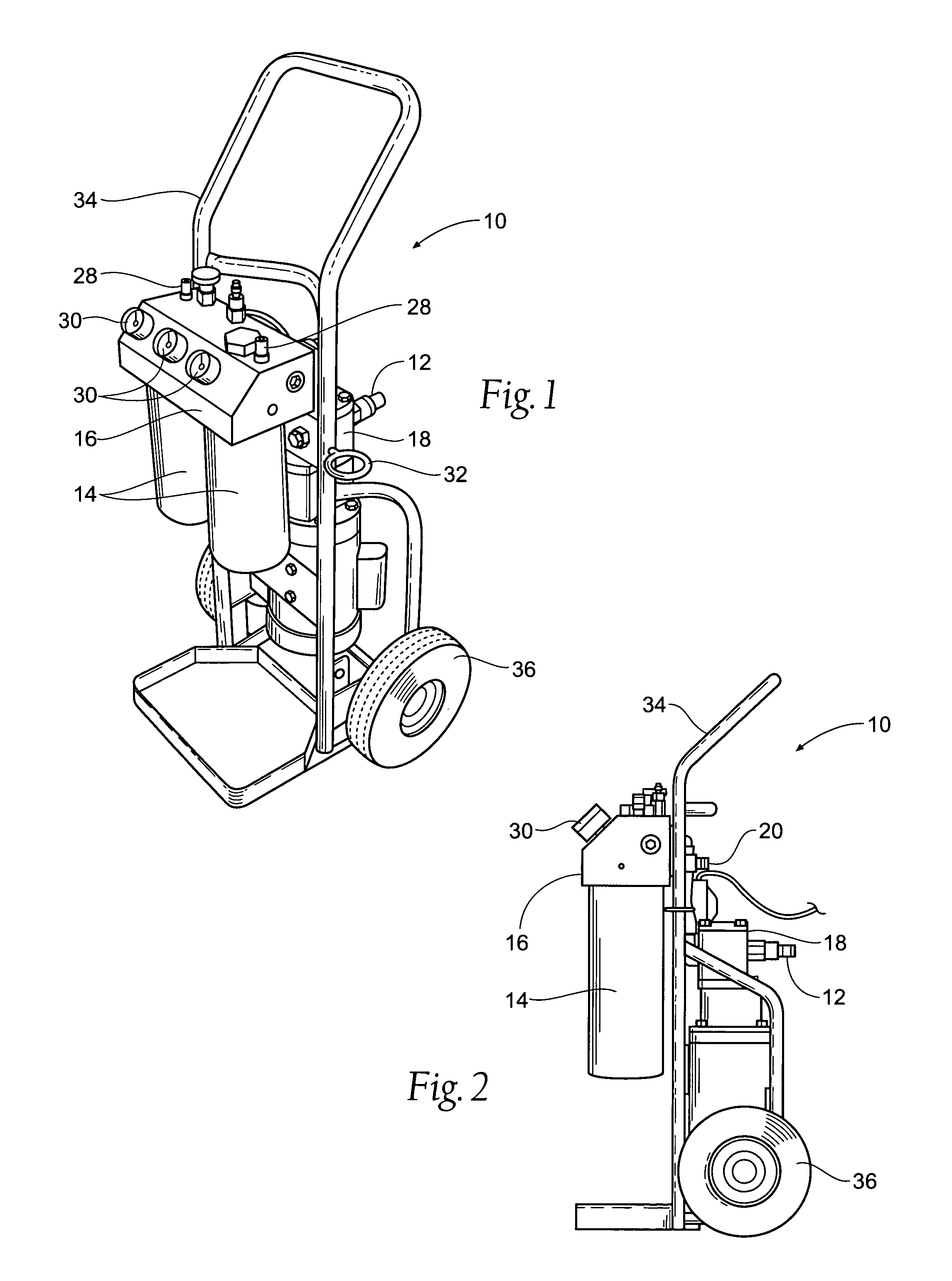
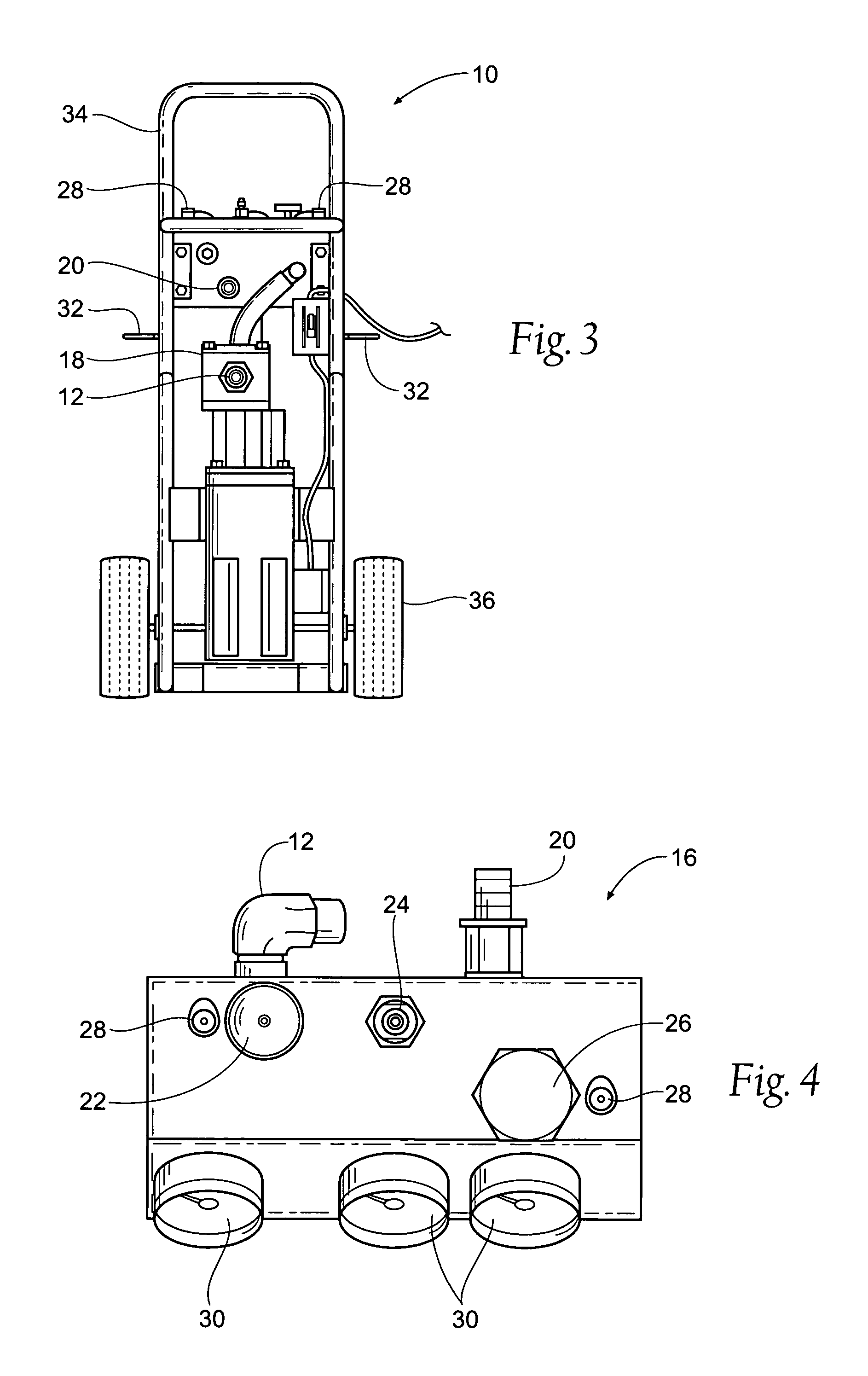
[0027]As may be seen in the Figures, the present portable lubricant filtration system 10 generally includes a lubricant inlet 12, through which lubricant is received into the system 10, at least one filter element 14, a distribution and control manifold 16, and either an electrical pump 18, preferably a internal gear pump, or pneumatic unit (not shown) if air driven pumps are available, or any other operable type of pumping mechanism. The lubricant inlet 12, may be coupled externally to a conventional retrieval wand system (not shown) to facilitate the intake of lubricant from various sources.

[002...


PUM

PropertyMeasurementUnit
pressureaaaaaaaaaa
frictionaaaaaaaaaa
viscosityaaaaaaaaaa

Abstract

A portable lubricant filtration system and method is provided for facile pre-filtering of used or new lubricant prior to pumping the lubricant into its intended machinery.

Description

BACKGROUND OF THE INVENTION[0001]Lubrication is an important aspect of maintaining machinery in proper operating condition. Machine elements such as bearings, journals, shafts, and joints require proper lubrication between their moving surfaces to decrease friction, prevent contamination, reduce wear and dissipate heat. Improper lubrication is likely to lead to premature component wear and component or system failure.[0002]When determining the optimal lubrication between moving machine elements, many factors should be considered. These factors include the mode of operation of the machine, the type of machine element to be lubricated, the environment of the machine, the operating speed of the machine, the lubricant's viscosity, the lubricant's temperature, the lubricant's ingredients, and the lubricant's condition.[0003]Lubricators supply a constant level of lubricant within a lubricant reservoir to a machine element. The lubricant level is predetermined for the particular applicatio...

Claims


Application Information

Patent Timeline
Patent Type & Authority Patents(United States)
IPC IPC(8): B01D29/56
CPCB01D29/606B01D35/143B01D35/147B01D35/1475B01D2201/265
Inventor WILSON, JAY
Owner TRICO CORP
Why Eureka
Try Eureka