Solid polymer fuel cell

a fuel cell and polymer technology, applied in the field of solid polymer fuel cells, can solve the problems of reducing the generation capacity and generation efficiency, reducing the output, and reducing the output, so as to reduce the number of components, reduce the size and weight of the fuel cell, and improve the productivity

Inactive Publication Date: 2012-04-03
NEC CORP
View PDF21 Cites 0 Cited by
  • Summary
  • Abstract
  • Description
  • Claims
  • Application Information

AI Technical Summary

Benefits of technology

[0027]The present invention allows manufacturing a vapor-feed fuel cell of a simplified structure in which a gas-liquid separation membrane encloses an assembly, to thereby improve the productivity and decrease the number of components, thus reducing the size and weight of the fuel cell. Moreover, a single component serves to perform the three functions of vaporizing the fuel to be supplied to the anode, which is essential in the vapor-feed fuel cell, discharging CO2 gas from the anode, and suppression of transpiration of the generated water.
[0028]The structure that a single piece of gas-liquid separation membrane held therein seals the assembly facilitates minimizing the probability that a liquid product generated inside the assembly may leak outward, to thereby stabilize the fuel supply balance. Consequently, a high generation characteristic and maintenance characteristic can be secured over a long period of time, despite the very simple structure.
[0029]Also, the structure that inhibits the leakage of the liquid product provides a significant benefit from the viewpoint of safety and reliability, when applied to electronic apparatuses including mobile phones and laptop computers.
[0030]Further, the inverse diffusion of the generated water from the cathode to the anode is further encouraged, which facilitates achieving a stabilized generation characteristic and maintenance characteristic over a long period of time.

Problems solved by technology

It is known, however, that in the case where the fuel concentration becomes higher and hence a relatively larger amount of alcohol fuel is supplied to the anode than water, what is known as “cross-over effect” takes place in which the alcohol fuel is transmitted through the solid polymer electrolytic membrane without being involved in the reaction represented by the formula (1), to be reacted with the catalyst on the cathode, which results in decreased generation capacity and generation efficiency.
Another drawback has come up, that in the case where the methanol concentration in the fuel is increased, water supply for the methanol becomes insufficient on the anode, which disables increasing the output.

Method used


Image

  • Solid polymer fuel cell
  • Solid polymer fuel cell
  • Solid polymer fuel cell

Examples


example 1

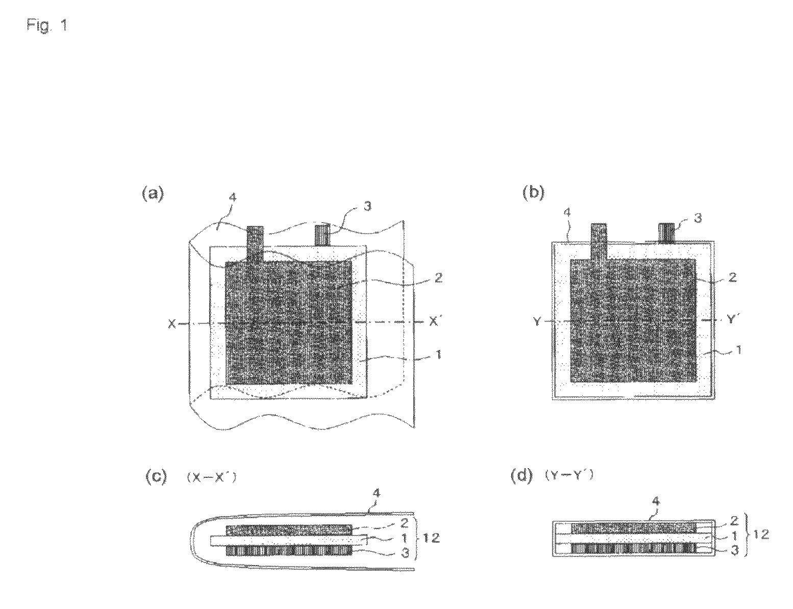
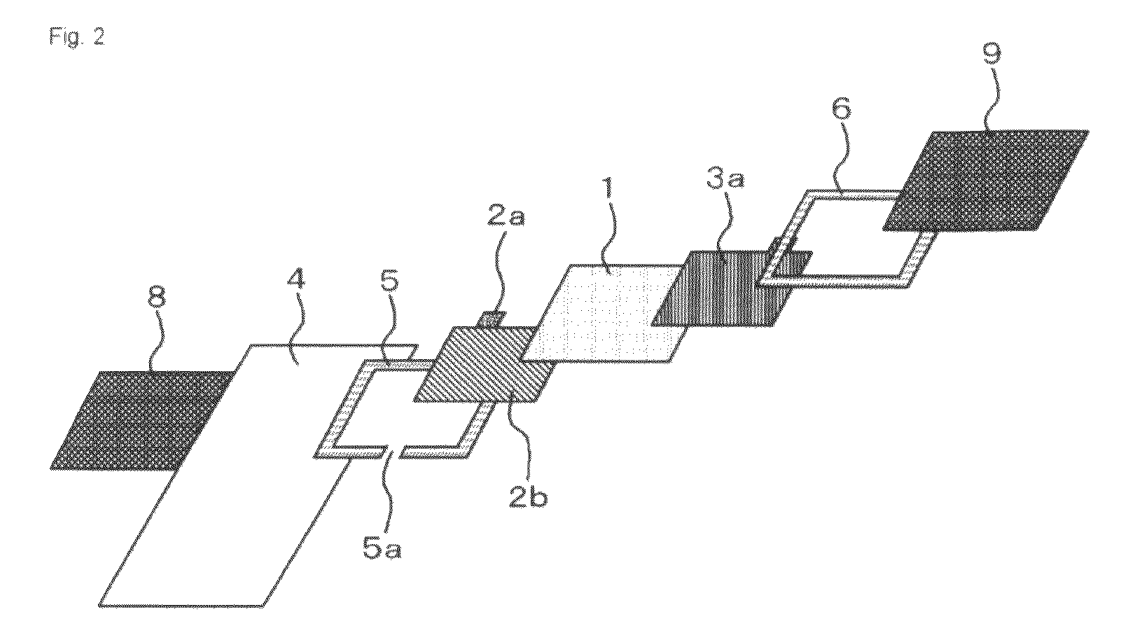
[0063]Hereunder, a solid polymer fuel cell according to the example 1 of the present invention will be described referring to a specific example. The single cell type solid polymer fuel cell shown in FIGS. 2 and 3 was made up through the following procedure (Ref. FIGS. 6(a) and 6(b)).

[0064]To form the cathode 3, firstly catalyst-carrying carbon fine particles, containing 55 wt. % of Pt fine particles of 3 to 5 nm in diameter in carbon particles (Ketjen Black EC600JD from Lion Corporation), were prepared, and an appropriate amount of 5 wt. % Nafion solution (Article No. DE521, “Nafion” is a registered trademark of E. I. du Pont de Nemours & Company (Inc.) was added to 1 g of the catalyst-carrying carbon fine particles and stirred, to thereby obtain a catalyst paste for the cathode (corresponding to the cathode catalyst layer 3b). The catalyst paste was applied to a metal porous base 3a at a rate of 1 to 8 mg / cm2 and dried, thus to make up the cathode 3. For the porous base 3a, a meta...

example 2

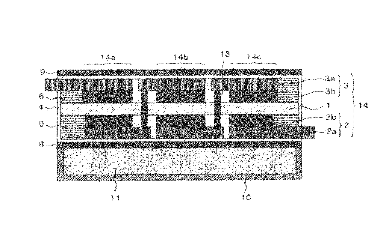
[0072]Hereunder, a solid polymer fuel cell according to the example 2 of the present invention will be described referring to a specific example. The solid polymer fuel cell of the serial unit structure shown in FIGS. 4 and 5 was made up through the following procedure (Ref. FIGS. 7(a) and 7(b)).

[0073]Firstly three pieces each of anodes 2 and cathodes 3 according to the example 1 were prepared. Then a film of Nafion 117 from DuPont was prepared as the solid polymer electrolytic membrane, in the size of 15 cm×5 cm and thickness of 180 μm. Regarding the solid polymer electrolytic membrane 1, the anode 2, and the cathode 3, the three anodes 2 were placed on one of the faces in the thickness direction of the solid polymer electrolytic membrane 1 such that the respective porous bases 2a were exposed as shown in FIG. 5, and such assembly was hot-pressed. In doing so, a positioning frame was employed on the solid polymer electrolytic membrane 1 so as to prevent the adjacent anodes 2 from b...

example 3

[0078]Hereunder, a solid polymer fuel cell according to the example 2 of the present invention will be described referring to a specific example. The single cell type solid polymer fuel cell shown in FIG. 3 was made up through the following procedure.

[0079]Firstly the MEA 12 (including the spacers 5, 6) was made up through a similar procedure to the example 1. Here, in the example 2 a polypropylene porous material (rectangular frame shape, outer size 45 mm, thickness 0.5 mm, width 5 mm, and porosity 50%) was employed as the spacers 5, 6.

[0080]Then the MEA 12 with the spacers 5, 6 attached thereto was enclosed in the gas-liquid separation membrane 4 with folding portions formed along the three sides so as to serve as the adhesion margins 4a (FIG. 8(a)) as shown in FIG. 8, and the adhesion margin 4a was folded toward the spacer 5 on the side of the anode 2, and the polyimide-based adhesive was then applied to the adhesion margin 4a and the assembly was sealed by thermo-compression bon...


PUM

PropertyMeasurementUnit
porosityaaaaaaaaaa
diameteraaaaaaaaaa
thickaaaaaaaaaa

Abstract

A solid polymer fuel cell includes a solid polymer electrolytic membrane 1, an anode 2 contacting one of the faces of the solid polymer electrolytic membrane 1, a cathode 3 contacting the other face of the solid polymer electrolytic membrane 1, and a gas-liquid separation membrane 4 enclosing a MEA 12 including the solid polymer electrolytic membrane 4, the anode 2, and the cathode 3, and which transmits gas but not liquid. An end face of the gas-liquid separation membrane 1 is sealed, and the MEA 12 is isolated from outside of the gas-liquid separation membrane 4. The anode 2 and the cathode 3 respectively include an electrode terminal extending from an end portion thereof, and the electrode terminal is exposed to outside of the gas-liquid separation membrane 4, through an end portion thereof. With such structure, a fuel is supplied in a form of vapor to the anode 2 through the gas-liquid separation membrane 4 opposing the anode 2, and a reaction product from the anode 2 is discharged through the gas-liquid separation membrane 4 located on a lateral side of the anode 2, and at least oxygen is supplied to the cathode 3 through the gas-liquid separation membrane 4 opposing the cathode 3.

Description

TECHNICAL FIELD[0001]The present invention relates to a solid polymer fuel cell that employs vaporized liquid fuel, and to a method of manufacturing the same.BACKGROUND ART[0002]Development of solid polymer fuel cells that employ alcohol fuel is being actively promoted for use as a power source for various electronic apparatuses including mobile phones, because such cells are easy to be made smaller in dimensions and lighter in weight. The development is primarily focused on solid polymer fuel cells that employ methanol fuel, owing to higher energy density thereby attained.[0003]The solid polymer fuel cell includes a Membrane and Electrode Assembly (hereinafter, MEA), in which a solid polymer electrolytic membrane is interleaved between an anode and a cathode. The fuel cell that directly supplies the liquid fuel to the anode is called a direct-type fuel cell, in which the supplied liquid fuel is decomposed on a catalyst carried by the anode, so that positive ion, electron and an int...

Claims


Application Information

Patent Timeline
Patent Type & Authority Patents(United States)
IPC IPC(8): H01M8/10H01M8/04
CPCH01M8/02H01M8/023H01M8/04089H01M8/0675H01M8/2475H01M2008/1095Y02E60/50
Inventor KOBAYASHI, KENJISEKINO, SHOJI
Owner NEC CORP
Why Eureka
Try Eureka