Phase difference detection device, imaging apparatus, phase difference detection method

a detection device and detection method technology, applied in the direction of color signal processing circuits, exposure control, camera focusing arrangement, etc., can solve the problems of detection error, detection error, deviation of the phase difference detection result of two image signals, etc., and achieve the effect of less susceptibl

Active Publication Date: 2012-04-03
CANON KK
View PDF9 Cites 52 Cited by
  • Summary
  • Abstract
  • Description
  • Claims
  • Application Information

AI Technical Summary

Benefits of technology

[0008]It is desirable to provide a phase difference detection device that is less susceptible to a phase difference detection error even for a pair of image signals having a gain difference.

Problems solved by technology

However, there are the following problems with the conventional phase difference detection methods.
At a position away from the center of the optical axis of an image-taking lens, an uneven decrease in light intensity from a pair of image signals occurs due to vignetting of an image-taking lens, resulting in a gain difference between two image signals.
An attempt to detect a phase difference between two image signals having a gain difference may result in not only detection difficulty caused by a poor degree of coincidence therebetween but may also result in detection error depending on the pattern of an image signal. FIG. 35A is a view showing the waveforms of two image signals when there is a gain difference.
As a result, the problem arises in that deviations in the phase difference detection result of two image signals will occur.
However, there exist the vignetting deviation due to manufacturing error on an image-taking lens, the vignetting deviation due to play of an image-taking lens during zoom / focus driving, and the aperture ratio deviation due to manufacturing fluctuations on a lens system that forms a pair of optical images, or the like.
Therefore, an error caused by these various factors still remains in gain correction, which may result in the gain difference as shown in FIG. 35A.
When such correction remains present, the problem also arises in that deviations in the phase difference detection result of two image signals will occur.

Method used


Image

  • Phase difference detection device, imaging apparatus, phase difference detection method
  • Phase difference detection device, imaging apparatus, phase difference detection method
  • Phase difference detection device, imaging apparatus, phase difference detection method

Examples


first embodiment

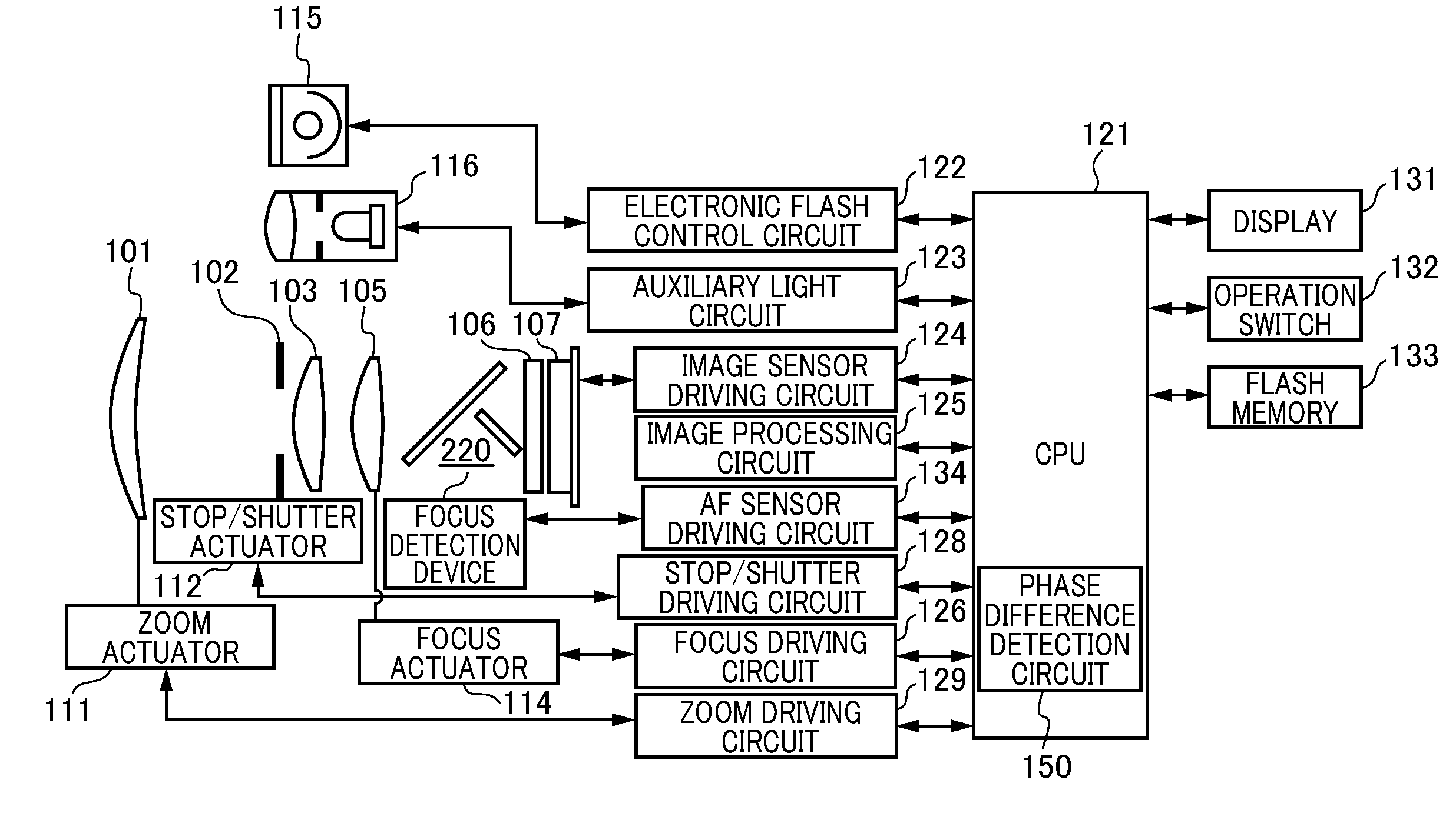
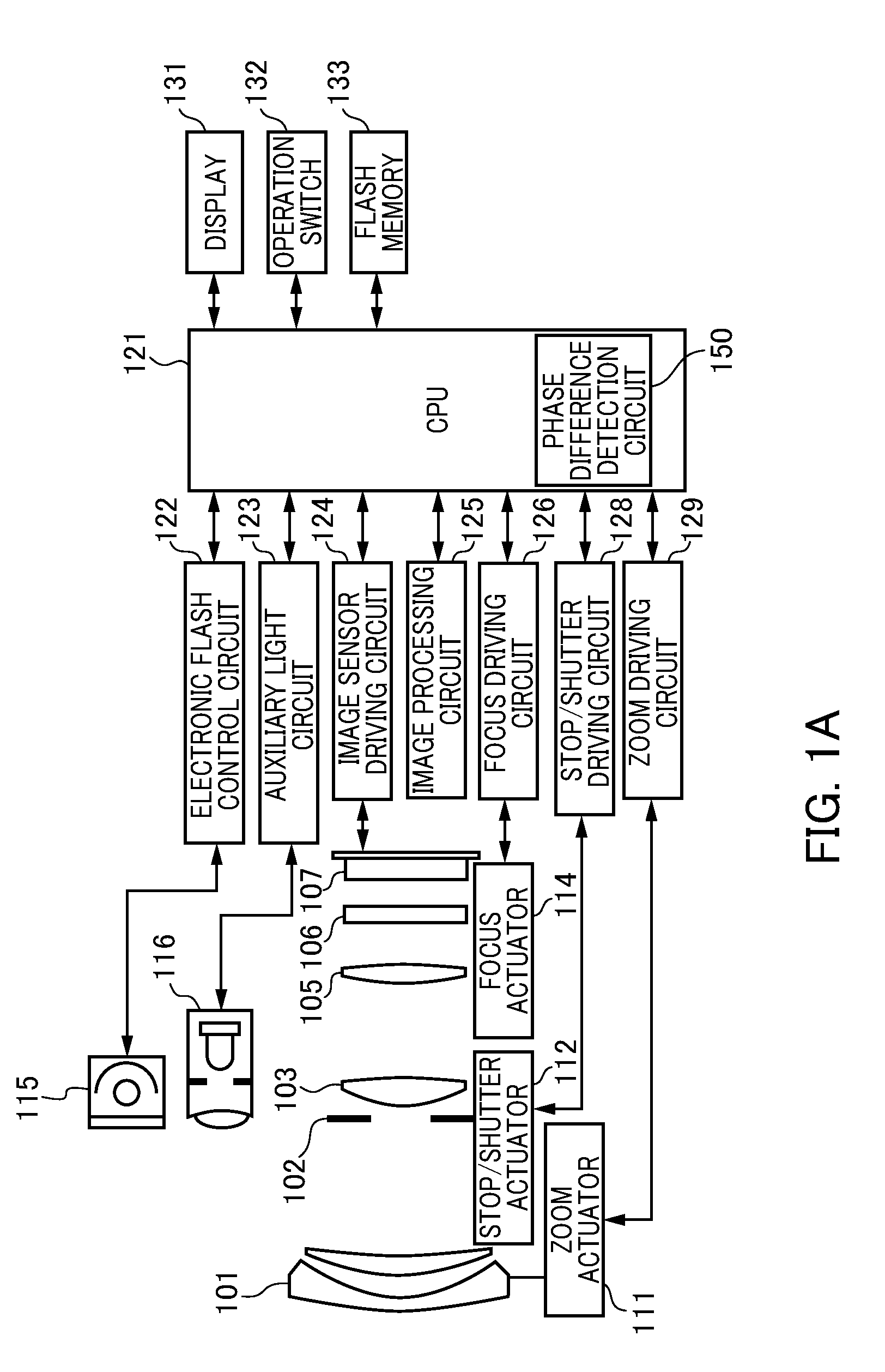
[0060]FIG. 1A is a view of the configuration of the camera of the first embodiment provided with the phase difference detection device of an embodiment of the present invention. The camera of the first embodiment is a digital camera that serves as an imaging apparatus integrating a camera body having an image sensor with a photographic optical system TL. The camera of the first embodiment includes a first lens group 101, a stop / shutter 102, a second lens group 103, a third lens group 105, a low-pass filter 106, an image sensor 107. In addition, the camera of the first embodiment includes a zoom actuator 111, a stop / shutter actuator 112, a focus actuator 114, an electronic flash 115, an AF auxiliary light unit 116, a CPU 121, an electronic flash control circuit 122. The camera of the first embodiment further includes an auxiliary light driving circuit 123, an image sensor driving circuit 124, an image processing circuit 125, a focus driving circuit 126, a zoom driving circuit 129, a ...

second embodiment

[0109]With reference to FIGS. 27 to 33, the second embodiment of the present invention will be described. In the first embodiment, the image sensor includes the image sensing pixels and the focus detection pixels, and the pupil is split by projecting an aperture biased toward the center of the microlens ML in the focus detection pixel onto the exit pupil of the photographic optical system 201. Then, by calculating a phase difference between a pair of obtained image signals from a pair of focus detection pixels having an aperture biased in the opposite direction, the focus state of the photographic optical system 201 is detected. In other words, the first embodiment is a phase difference focus detection method of the TTL (through the lens) primary image-forming type. In the second embodiment, a light beam guided by the optical path splitting between the photographic optical system 201 and the image sensor is reimaged by a secondary image forming optical system composed of a pair of l...

third embodiment

[0129]In the second embodiment, a light beam guided by the optical path splitting between the photographic optical system 201 and the image sensor 204 is reimaged by a secondary image forming optical system (reimaging lens 214) composed of a pair of lens elements. Then, the focus state of the photographic optical system 201 on the basis of the phase difference between a pair of obtained image signals was described. In other words, the second embodiment is a phase difference focus detection method of the TTL secondary image-forming type. In the third embodiment, in addition to the photographic optical system, there is separately provided a focus detection optical system, whereby focus detection is performed by the triangulation principle. In other words, the phase difference focus detection method of the external measuring type is a feature of the third embodiment.

[0130]FIG. 34 is a view showing a configuration of a camera of the third embodiment. The camera of the third embodiment i...


PUM


Abstract

The ratio between an image A and an image B is calculated as the comparison result of the images A and B obtained from a pair of optical images. The variance is then calculated in order to evaluate the statistical fluctuation of the ratio obtained for each pixel. The fluctuation due to the variance is evaluated for each phase difference while the phase between the image A and the image B is shifted. The phase difference detection is performed on the basis of the evaluation result of the fluctuation.

Description

BACKGROUND OF THE INVENTION[0001]1. Field of the Invention[0002]The present invention relates to a phase difference detection device which can be employed on an imaging apparatus such as a camera or a video camera, an imaging apparatus including the phase difference detection device, a phase difference detection method, and a computer-readable recording medium containing computer program code for causing a computer to carry out the phase difference detection method.[0003]2. Description of the Related Art[0004]In conventional imaging apparatuses, the focus state of an image-taking lens is detected in an autofocus (AF) operation. For example, a focus detection method is known that is for detecting a focus state of an image-taking lens from a phase difference between a pair of image signals between which the relative position relationship changes depending on the focus state of the image-taking lens. A method for detecting a phase difference between a pair of image signals on the basis...

Claims


Application Information

Patent Timeline
Patent Type & Authority Patents(United States)
IPC IPC(8): H04N5/232H04N9/64H04N5/238G06K9/46G03B13/00G03B7/099G01D5/34G06K9/40G02B7/28G02B7/34G03B13/36H04N101/00
CPCH04N5/23212G03B13/36H04N23/672
Inventor OIKAWA, MAKOTO
Owner CANON KK
Why Eureka
Try Eureka