Device and method for green machining bevel gears

a technology of bevel gears and green machining, which is applied in the direction of gear teeth, manufacturing tools, transportation and packaging, etc., can solve the problems of restricted movement clearance, difficult preparation of bevel gears, and high cost of machine tools, and achieve the effect of simplifying the manufacturing of bevel gears

Inactive Publication Date: 2012-04-10
KLINGELNBERG AG
View PDF12 Cites 19 Cited by
  • Summary
  • Abstract
  • Description
  • Claims
  • Application Information

AI Technical Summary

Benefits of technology

[0007]The present invention is based on the object of simplifying the manufacturing of bevel gears on one hand and accelerating it on the other hand, without having to accept quality losses.

Problems solved by technology

One solution, which has only been able to succeed in a limited way up to this point, however, is a machining center which is designed so that a large number of manufacturing steps may be executed on the same machine tool.
Such machine tools are not only very complex and therefore costly, but rather also require relatively great effort in the preparatory set up (equipping time).
It is seen as a disadvantage of this machine tool that, because of the configuration of the various elements, it is not designed for the purpose of executing dry machining, because the removal of the hot chips is of special significance during dry machining.
In addition, the movement clearance is restricted by the lateral configuration of the two carriages having the tools in relation to the workpiece.
It is seen as a disadvantage of the machine tools which machine a workpiece in multiple steps without rechucking the workpiece that a large number of different parameters have to be taken into consideration in the design and implementation of the machine tool.
If one also wishes to perform a part or all of the cited steps as dry machining, further restrictions in regard to the configuration of the individual axes and tools result because of the special requirements in dry machining for the removal of the hot chips.

Method used


Image

  • Device and method for green machining bevel gears
  • Device and method for green machining bevel gears
  • Device and method for green machining bevel gears

Examples


Embodiment Construction

[0022]Terms which are also used in relevant publications and patents are used in connection with the present description. However, it is to be noted that the use of these terms is solely for better understanding. The inventive ideas according to the present invention and the scope of protective of the patent claims are not to be restricted in their interpretation by the specific selection of the terms. The present invention may be transferred without further measures to other term systems and / or professional fields. The terms are to be applied accordingly in other professional fields.

[0023]The present invention is concerned with the machining of bevel gears. According to the definition, this term also comprises ring gears and bevel pinions. Bevel gears without axial offset and bevel gears with axial offset, i.e., so-called hypoid gears, are also included.

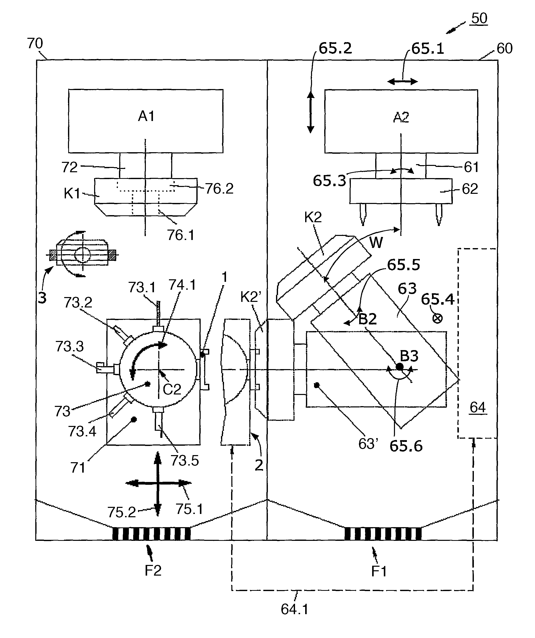
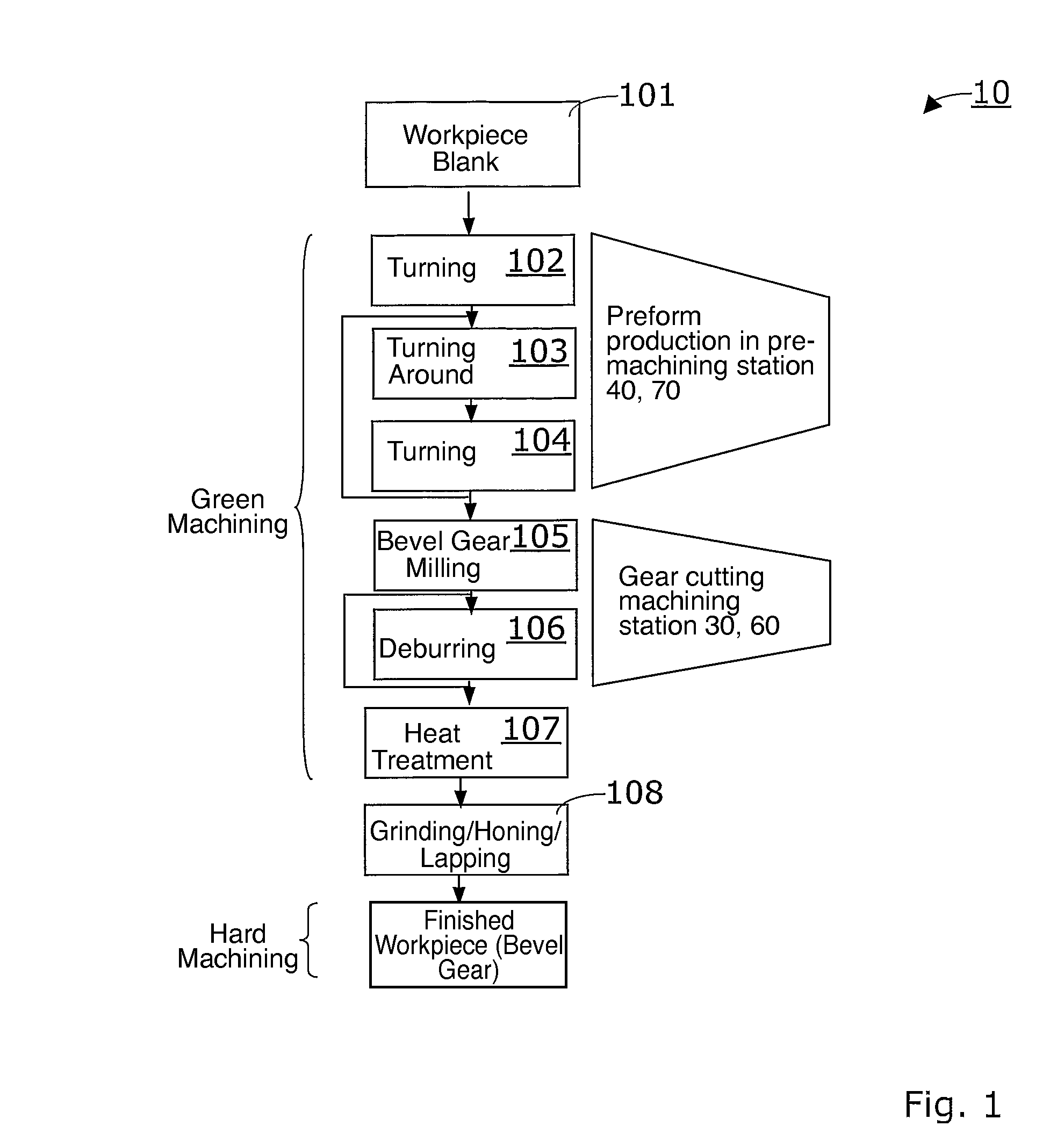
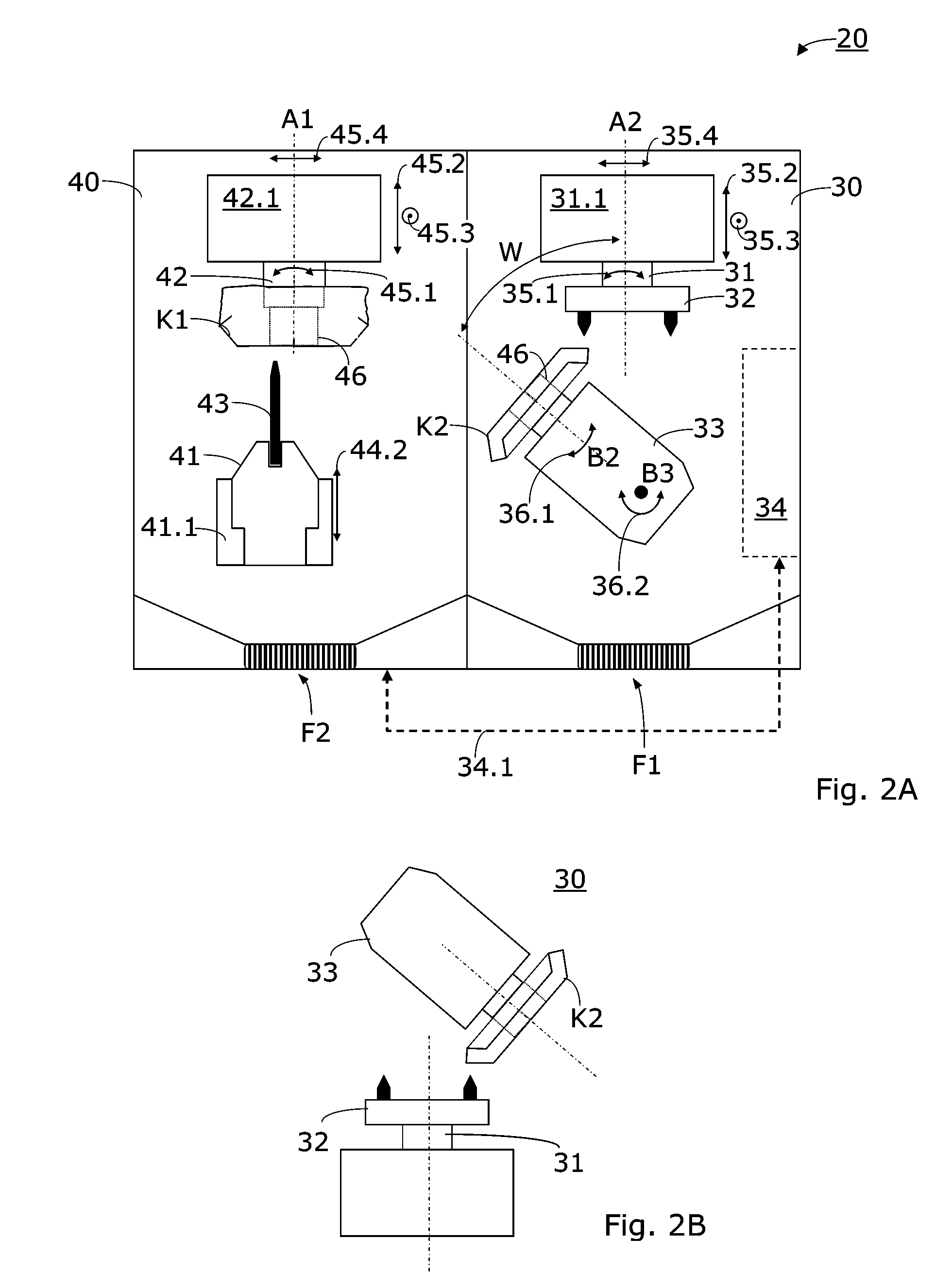
[0024]FIG. 1 shows a schematic illustration of an exemplary method sequence 10. The present invention may advantageously be used i...


PUM

PropertyMeasurementUnit
angleaaaaaaaaaa
angleaaaaaaaaaa
flexibilityaaaaaaaaaa

Abstract

The invention relates to a device for green machining bevel gears, including a CNC machining station for gear cutting a wheel blank (K2). The machining station includes a tool spindle which is used to receive a gear cutting tool and a work piece spindle which is used to receive the gear blank (K2). The machining station also relates to a machining station which operates in a vertical manner. The device also comprises a vertical processing station having a tool holder and a work piece spindle which is used to receive a work piece blank (K1). The machining station mechanically forms a functional unit together with the pre-machining station, wherein the work piece blank (K1) undergoes green machining in the pre-machining station, and is transferred as a gear blank (K2) to the first machining station after the first green machining where it is cut into a gear. The machining station and the pre-machining station are linked together in terms of data and control.

Description

CROSS REFERENCE TO RELATED APPLICATION[0001]This application claims the benefit of PCT Application No. PCT / EP2005 / 001478, filed Feb. 14, 2005, the disclosure of which is herein incorporated by reference in its entirety.BACKGROUND OF THE INVENTION[0002]The present invention relates to devices for green machining bevel gears, in particular devices which are designed for dry machining. The present invention also relates to a corresponding method.[0003]There are greatly varying machine tools which are used in the manufacture of bevel gears and similar gears. For some time, there has been a wish for automating the manufacture. One solution, which has only been able to succeed in a limited way up to this point, however, is a machining center which is designed so that a large number of manufacturing steps may be executed on the same machine tool. Such machine tools are not only very complex and therefore costly, but rather also require relatively great effort in the preparatory set up (equ...

Claims


Application Information

Patent Timeline
Patent Type & Authority Patents(United States)
IPC IPC(8): B23P23/00B23P15/14B23F17/00B23Q39/04B23Q7/04B23Q7/00
CPCB23F17/008B23F17/003B23P15/14Y10T409/100954Y10T409/309408Y10T409/104611Y10T29/5124Y10T29/5127Y10T409/303752Y10T29/5176Y10T409/107791Y10T409/108268Y10T409/100795Y10T29/49476Y10T409/10795Y10T29/5136Y10T409/108586Y10T409/104134Y02P70/10
Inventor MULLER, HARTMUTHTHOMAS, JOACHIMRIBBECK, KARL-MARTINSCHNEIDER, BURKHARDLOH, DIETMAR
Owner KLINGELNBERG AG
Why Eureka
Try Eureka