Supercharge Your Innovation With Domain-Expert AI Agents!

High dynamic range NDT/NDI inspection device with selective noise averaging

a technology of selective noise and inspection device, which is applied in the direction of instruments, specific gravity measurement, code conversion, etc., can solve the problems of affecting the troubleshooting and repair of inspection devices, especially difficult problems, calibration, reliability, etc., and achieves the effect of reducing inspection measurement performance and high manufacturing cos

Active Publication Date: 2012-04-17
OLYMPUS AMERICA
View PDF7 Cites 0 Cited by
  • Summary
  • Abstract
  • Description
  • Claims
  • Application Information

AI Technical Summary

Benefits of technology

The solution enables high-performance ultrasonic inspection with reduced hardware costs and increased miniaturization, maintaining high dynamic range sensitivity and accuracy, with the ability to represent measurements in logarithmic or linear amplitude scales.

Problems solved by technology

In general, this group of UT systems utilizes highly complex analog front ends that contain many parts which pose especially difficult problems in terms of calibration, reliability, set up time, consistency of results and optimization for specific usages and settings.
As a result, this group of UT systems presents limitations and drawbacks to designers and users of such equipment, which impact their troubleshooting and repair owing to their complexity.
More specifically, the limitations include such issues as matching input impedances seen by the probe system which changes with different gain amplifiers that are switched in and out of the signal path.
This adversely impacts the frequency response and introduces various gain nonlinearities.
It poses issues of calibration, as analog circuits are switched in and out of the signal path.
However, Parallel HDR digitizer designs present the drawbacks associated with using two or more analog to digital converters.
Such drawbacks include elevated hardware cost and the need for more circuit board space which is undesirable for a highly miniaturized product.

Method used


Image

  • High dynamic range NDT/NDI inspection device with selective noise averaging
  • High dynamic range NDT/NDI inspection device with selective noise averaging
  • High dynamic range NDT/NDI inspection device with selective noise averaging

Examples


Embodiment Construction

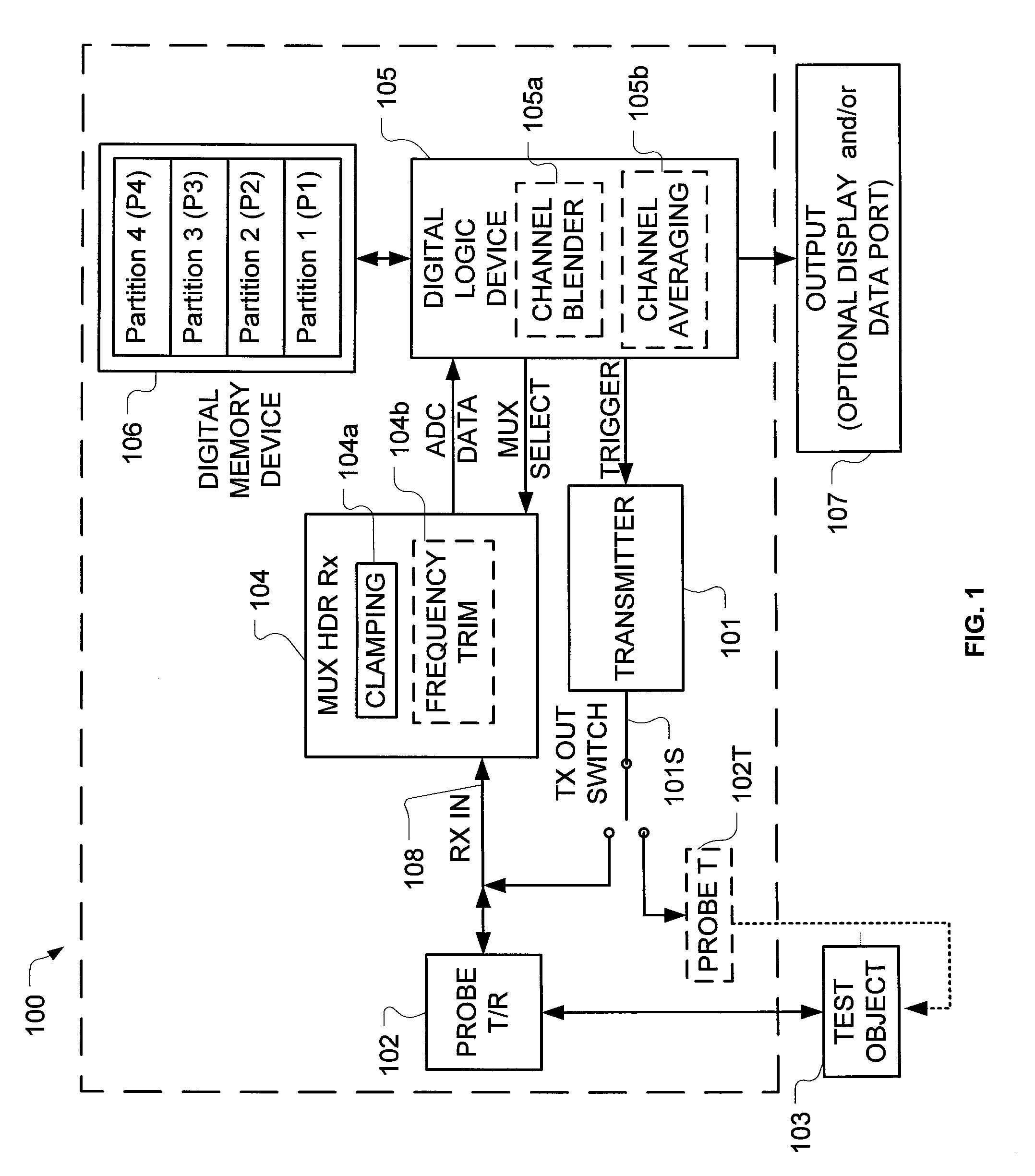
[0025]Referring to FIG. 1, the preferred embodiment of a Sequentially Fired High Dynamic Range Inspection Device 100 comprises a transmitter 101 driving a probe system 102, or 102T and a multiplexed high dynamic range receiver (MUX HDR Rx) 104 coupled to receive signals from the probe system 102. As can be well understood by those skilled in the art, device 100 may be optionally configured to operate in the ‘pulse-echo’ or ‘thru-transmission’ mode. Device 100 is in ‘pulse-echo’ mode when probe system 102 is connected to receiver 104 and transmitter 101 by TX OUT switch 101S. Device 100 is in ‘thru-transmission’ mode when probe system 102 is connected only to receiver 104 and probe 102T is connected only to transmitter 101 by TX OUT switch 101S. When in ‘thru-transmission’ mode, probe system 102 receives response signals resulting from the acoustic energy imparted by probe 102T on the opposite side of test object 103. A digital logic device (DLD) 105, a Digital Memory Device 106, and...


PUM

PropertyMeasurementUnit
frequency bandwidthaaaaaaaaaa
eddy current probeaaaaaaaaaa
electrical poweraaaaaaaaaa

Abstract

An apparatus for performing ultrasonic inspection of an object, during one measurement on the object, triggers a sequence of excitations of the probe system and receives a sequence of substantially identical echo signals reflected from the object, and further scales each echo signal to different degrees to increase and extend the dynamic range of the echo signals. An A / D converter is then used to digitize the scaled signal sequentially in a manner which dispenses the need for using numerous A / D converters and the associated filters. The digitized signal samples are then combined to produce a single digital output in a manner that is not over-flowed and with desirable resolution. A sequence of successive acquisitions of the scaled signal with the highest sensitivity are averaged to reduce system noise.

Description

FIELD OF THE INVENTION[0001]The present invention relates to non-destructive testing and inspection devices (NDT / NDI) and more particularly, to a high dynamic range analog to digital conversion system and method which utilizes selectively a sequence of pulse-receive acquisition cycles to realize a low noise single high dynamic range measurement.BACKGROUND OF THE INVENTION[0002]The testing and examination of complex structures, without damaging them, is now of great importance in a wide range of industrial situations. The use of NDT / NDI ultrasound (UT), phased-array (PA), and eddy current (EC) measurement modalities are perhaps the most ubiquitous such methodology. UT methods are now used to measure the geometric properties (such as thickness) of test objects, and detect and characterize static defects or anomalies in metal, non-metal, or fiber composite structures in real time. EC methods are now used to detect and characterize static defects or anomalies in metal structures in real...

Claims


Application Information

Patent Timeline
Patent Type & Authority Patents(United States)
IPC IPC(8): G01N29/00H03M1/12
CPCG01N27/90G01N29/04G01N29/32G01N29/449H03M1/1215H03M1/1225
Inventor THOMAS, ANDREW
Owner OLYMPUS AMERICA
Features
  • R&D
  • Intellectual Property
  • Life Sciences
  • Materials
  • Tech Scout
  • Unparalleled Data Quality
  • Higher Quality Content
  • 60% Fewer Hallucinations
Learn More