
Separator and separator seal for polymer electrolyte fuel cells

a technology of separator seal and polymer electrolyte, which is applied in the direction of fuel cell details, fuel cell, electrochemical generators, etc., can solve the problems that the elasticity of silicon rubber obtained by curing the addition cure type composition is still unsatisfactory over a long term, and achieves excellent sealing performance, reduced compression set, and effective moldability

Active Publication Date: 2012-04-17
HONDA MOTOR CO LTD +1
View PDF25 Cites 0 Cited by
  • Summary
  • Abstract
  • Description
  • Claims
  • Application Information

AI Technical Summary

Benefits of technology

The invention provides a separator seal for use in polymer electrolyte fuel cells that is made of cured rubber. The seal has ease of molding, reduced compression set, and satisfactory seal performance. The seal is formed at the periphery of a separator substrate and is made of a liquid silicone rubber composition that includes specific components. The composition has a viscosity at a certain temperature and a certain shear rate. The invention also provides a separator for use in polymer electrolyte fuel cells that includes a substrate and a seal formed at a periphery on at least one surface of the substrate. The seal is made of a cured product of the sealing composition.

Problems solved by technology

However, silicone rubbers obtained by curing the addition cure type compositions are still unsatisfactory in maintaining elasticity over a long term.

Method used

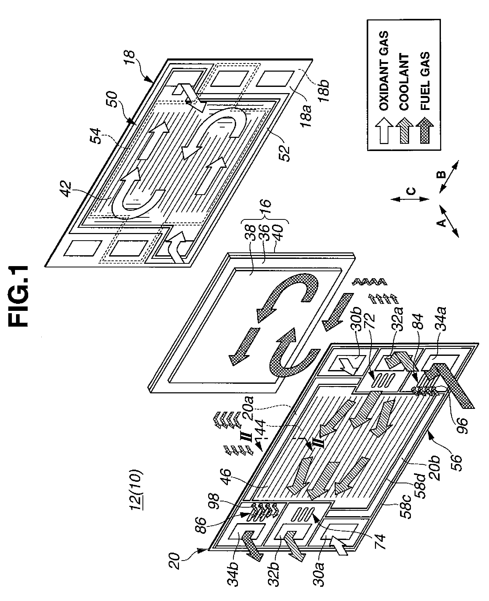
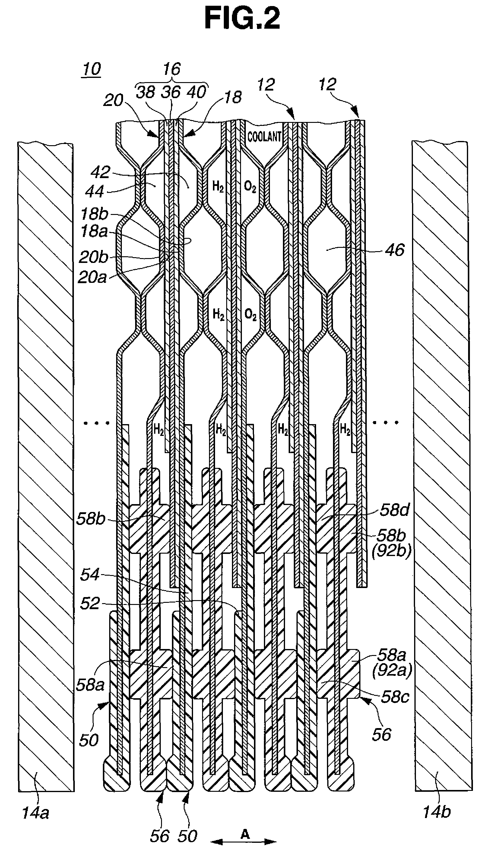
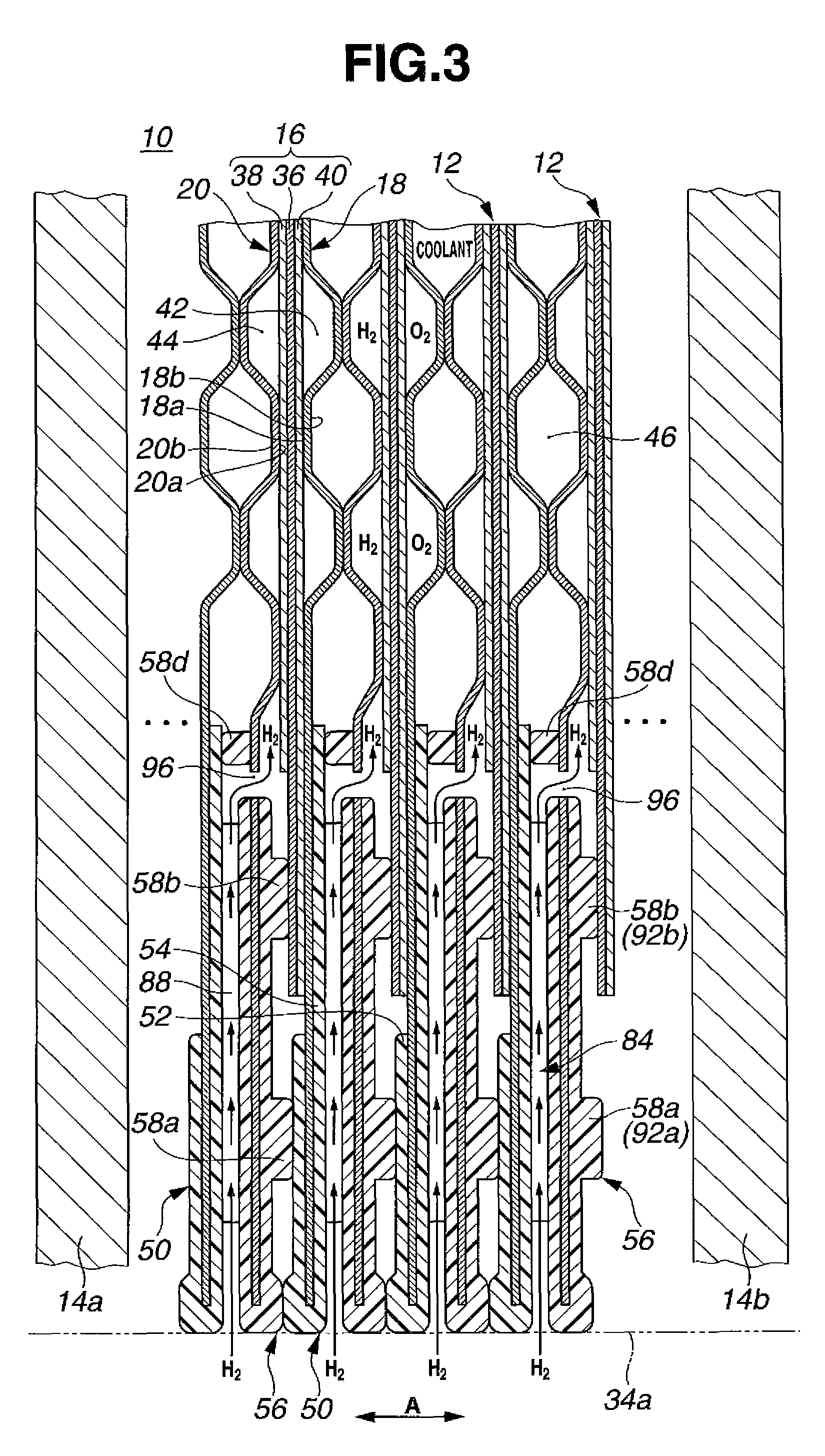

Image

  • Separator and separator seal for polymer electrolyte fuel cells
  • Separator and separator seal for polymer electrolyte fuel cells
  • Separator and separator seal for polymer electrolyte fuel cells

Examples


example 1

[0096]70 parts of dimethylpolysiloxane #1 capped with dimethylvinylsiloxy at both ends and having a Mw of 26,000 and a vinyl content of 0.000088 mol / g and 10 parts of gum-like dimethylpolysiloxane #2 capped with dimethylvinylsiloxy at both ends, containing vinyl on side chains, and having a Mw of 370,000 and a vinyl content of 0.00052 mol / g were mixed with 30 parts of fumed silica having a BET specific surface area of 200 m2 / g (Aerosil 300, Nippon Aerosil Co., Ltd.), 6 parts of hexamethyldisilazane, and 2.0 parts of water at room temperature for 30 minutes. The mixture was heated at 150° C., agitated at the temperature for 3 hours, and cooled. The mixture was further combined with 50 parts of dimethylpolysiloxane #1 and milled for 30 minutes, yielding a silicone rubber base. To 160 parts of the silicone rubber base were added 3.3 parts (giving [Si—H / vinyl]=1.5 in molar ratio) of methylhydrogenpolysiloxane #3 capped with dimethylsiloxy at both ends, containing Si—H groups at ends and...

example 2

[0098]43 parts of dimethylpolysiloxane #4 capped with dimethylvinylsiloxy at both ends and having a Mw of 18,000 and a vinyl content of 0.00011 mol / g, 20 parts of dimethylpolysiloxane #5 capped with trimethylsiloxy at both ends, containing vinyl on side chains and having a Mw of 42,000 and a vinyl content of 0.00007 mol / g and 12 parts of gum-like dimethylpolysiloxane #6 capped with dimethylvinylsiloxy at both ends, containing vinyl on side chains and having a Mw of 450,000 and a vinyl content of 0.000022 mol / g were mixed with 35 parts of fumed silica surface treated to be hydrophobic and having a BET specific surface area of 260 m2 / g (Rheorosil DM30S, Tokuyama Co., Ltd.), 5 parts of hexamethyldisilazane, and 1.0 part of water at room temperature for 30 minutes. The mixture was heated at 150° C., agitated at the temperature for 3 hours, and cooled. The mixture was further combined with 50 parts of dimethylvinylsiloxy-endcapped dimethylpolysiloxane #4 and milled for 30 minutes, yieldi...


PUM

PropertyMeasurementUnit
BET specific surface areaaaaaaaaaaa
viscosityaaaaaaaaaa
thicknessaaaaaaaaaa

Abstract

A rubber composition comprising (A) a liquid alkenyl-containing organopolysiloxane with Mw<100,000, (B) a gum-like organopolysiloxane with Mw≧150,000, (C) an organohydrogenpolysiloxane, (D) fumed silica, and (E) an addition reaction catalyst and having a viscosity of 20-200 Pa-s at a shear rate of 10 s−1 and 25° C. is effectively injection moldable into a cured product which is useful as a separator seal in PEFCs.

Description

CROSS-REFERENCE TO RELATED APPLICATION[0001]This non-provisional application claims priority under 35 U.S.C. §119(a) on Patent Application No. 2007-317475 filed in Japan on Dec. 7, 2007, the entire contents of which are hereby incorporated by reference.TECHNICAL FIELD[0002]This invention relates to separators and separator seals for use in polymer electrolyte fuel cells (PEFC) featuring compactness and more particularly, to separators and separator seals for PEFC which have a long service life and ease of molding.BACKGROUND ART[0003]The fuel cell is capable of producing electricity without a substantial need for fossil fuel that poses concerns about resource depletion, without noise, and at a high energy recovery rate as compared with other energy-based power generating systems. Great efforts have been made to exploit the fuel cell as a power generating plant of relatively compact size in buildings and factories, with some cells having been commercially implemented. In particular, p...

Claims


Application Information

Patent Timeline
Patent Type & Authority Patents(United States)
IPC IPC(8): H01M8/10C08L83/04
CPCH01M8/0282H01M2008/1095Y02E60/50
Inventor OKONOGI, DAISUKETERADA, SATORUMEGURIYA, NORIYUKIHAYASHIDA, OSAMU
Owner HONDA MOTOR CO LTD
Learn More