Electric power conversion system

a technology of electric power conversion and conversion system, which is applied in the direction of dc-ac conversion without reversal, electric apparatus casing/cabinet/drawer, application, etc., can solve the problems of reducing the life of the elements, and reducing the cooling performance of the electric power conversion system. , to achieve the effect of enhancing the cooling performance of the electric power conversion system

a technology of electric power conversion and conversion system, which is applied in the direction of dc-ac conversion without reversal, electric apparatus casing/cabinet/drawer, application, etc., can solve the problems of reducing the life of the elements, and reducing the cooling performance of the electric power conversion system. , to achieve the effect of enhancing the cooling performance of the electric power conversion system

US8159820B2Active Publication Date: 2012-04-17HITACHI IND EQUIP SYST CO LTD

Image

  • Electric power conversion system
  • Electric power conversion system
  • Electric power conversion system

Examples


Embodiment Construction

[0021]While several embodiments in accordance with the invention are shown and described, it should be understood that changes and modifications may be made to the disclosed embodiments without departing from the scope of the invention. Accordingly, the following description should not be taken as limiting the scope of the invention, which is defined in the claims.

[0022]A specific embodiment of the invention is described hereinafter with reference to FIGS. 1 to 7.

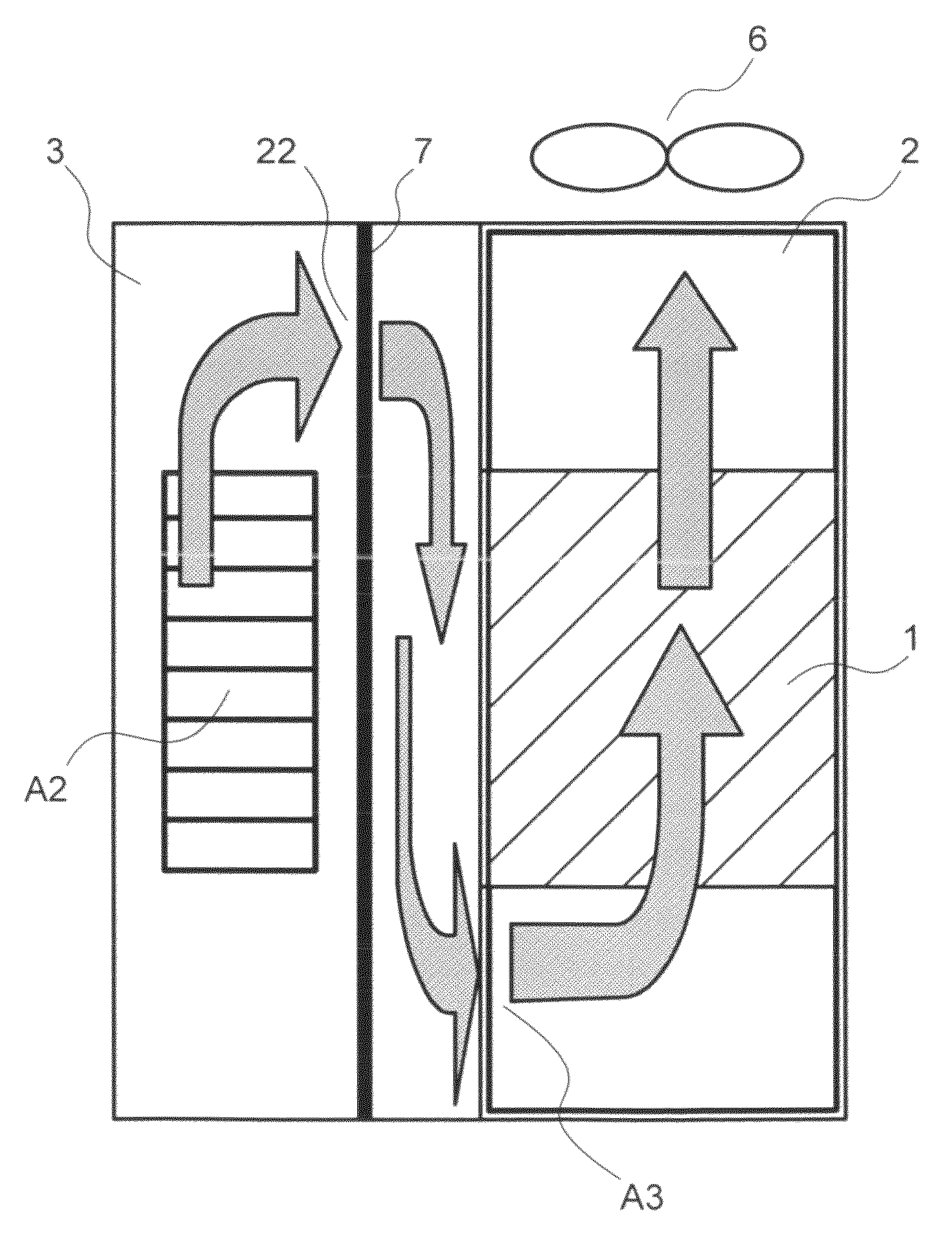
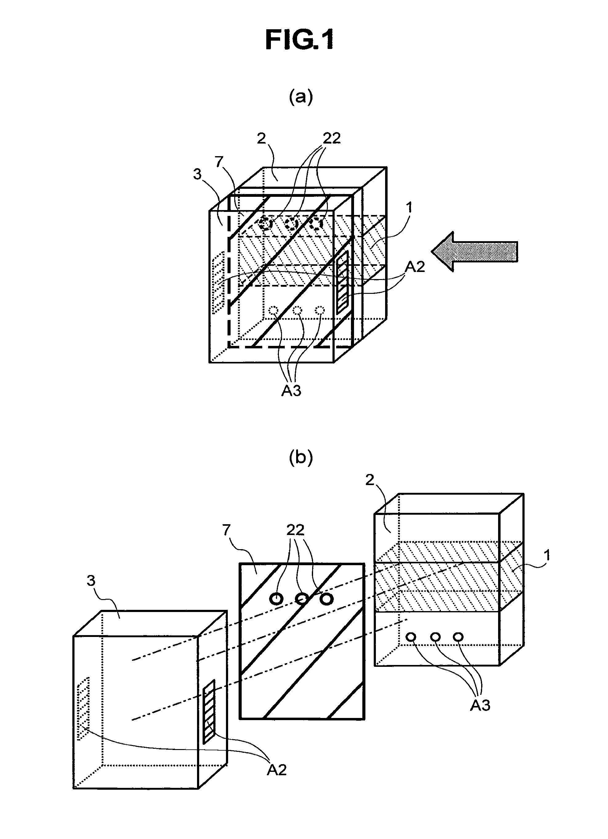
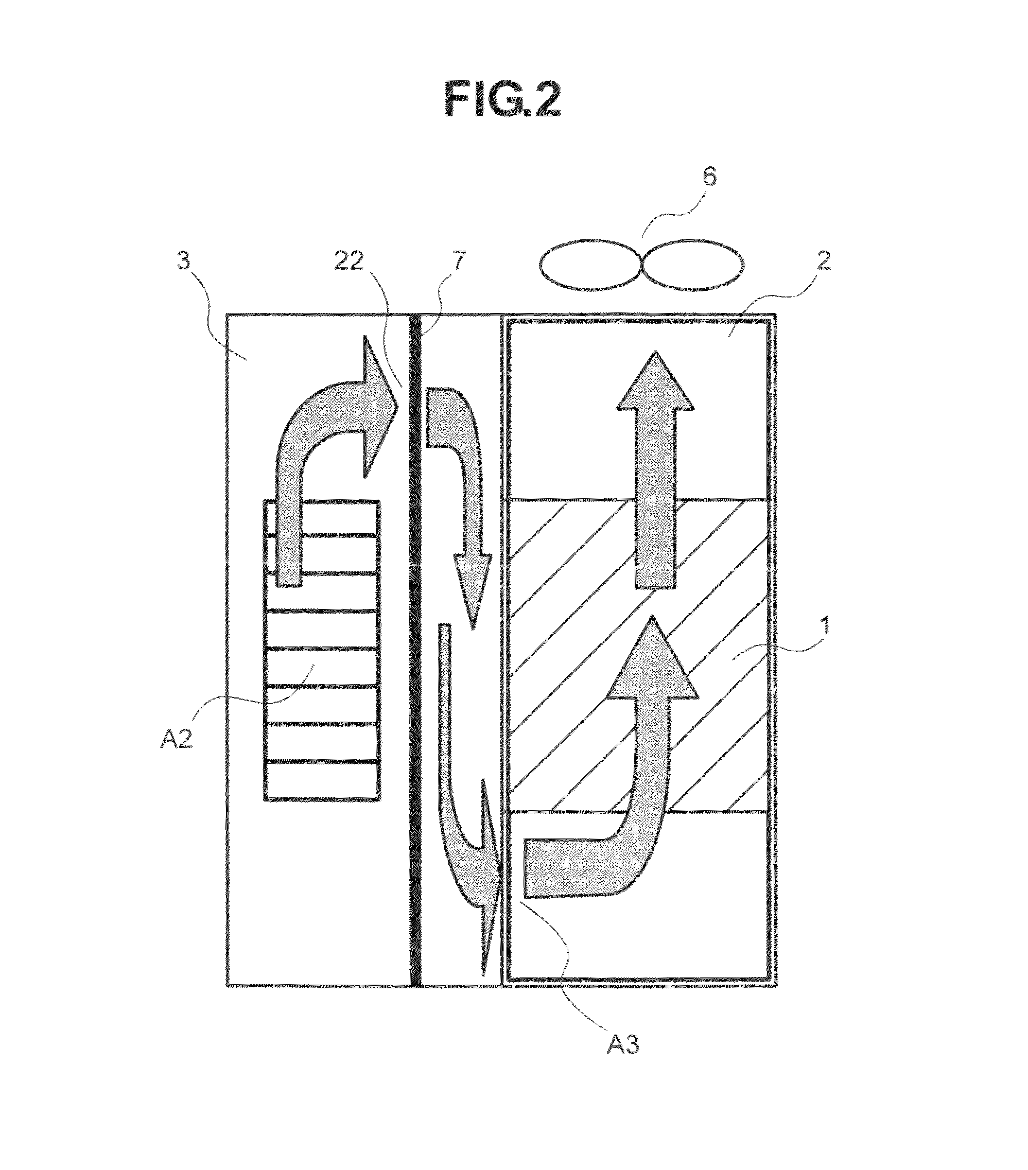
[0023]An embodiment of an electric power conversion system according to the invention is described hereinafter. FIG. 1(a) is a schematic perspective view of the electric power conversion system according to the present embodiment, and FIG. 1(b) is a schematic exploded view thereof. FIG. 1(a) is the perspective view of the system when installed, and the system is assembled by connecting a body cover (cover 3) at the front of the system with a body case (casing 2) on the back side thereof. Further, FIG. 1(b) is an exploded vi...


PUM


Abstract

In the present invention, miniaturization of an electric power conversion system is made possible while the reduction of a rise in temperature is achieved through a cooling operation by a cooling fan. The electric power conversion system is provided with a casing for covering cooling fins for cooling power semiconductors, a main circuit board having a driver circuit for driving the power semiconductors, and a cover for covering up the main circuit board. The system includes a first airflow hole provided at a part of the main circuit board, on the upper side of an air-intake provided in the cover, and a second airflow hole provided on the lower side of the first airflow hole, and on the lower side of the cooling fins, wherein air from the second airflow hole is driven to the cooling fins by a cooling fan.

Description

CROSS-REFERENCES TO RELATED APPLICATIONS[0001]The present application claims priority from Japanese application serial no. JP 2007-196892, filed on Jul. 30, 2007, the content of which is hereby incorporated by reference into this application.BACKGROUND OF THE INVENTION[0002]The invention relates to an electric power conversion system.[0003]Inverters are a type off electric power conversion systems that have been in widespread use as speed controllers of motors in both industrial apparatuses and household appliance products. However, power semiconductors for use in power conversion, such as IGBTs used in such electric power conversion systems, generate heat due to electrical energy loss at the time of power conversion, and the power semiconductors therefore normally have a predetermined operating temperature limit. If power semiconductors continue to generate heat after their temperature exceeds the operating temperature limit, the risk arises that the power semiconductors may stop o...

Claims


Application Information

Patent Timeline
17 Apr 2012
Publication
US8159820B2
IPC
H05K7/20
CPC
H02M7/003; H05K7/20909; H01L2924/0002; H01L23/4006; H01L23/467; H01L23/642; H01L25/072; H01L2924/00
Inventors
IBORI, SATOSHI; HAMANO, KOJI