Radio clock and method for extracting time information

a radio clock and time information technology, applied in the field of radio clocks and methods for extracting time information, can solve the problems of incorrect evaluation of at least one data bit of the minute record, erroneous reception of time information, etc., and achieve the effect of improving system sensitivity and simple adaptation

Active Publication Date: 2012-04-17
ATMEL CORP
View PDF30 Cites 0 Cited by
  • Summary
  • Abstract
  • Description
  • Claims
  • Application Information

AI Technical Summary

Benefits of technology

[0015]It is therefore an object of the present invention to provide a method and a circuit arrangement such that improved system sensitivity is achieved in a receiver for receiving time signals. In particular, the frequency of occurrence of errors due to misreading of pulse lengths is to be reduced, and distorted received signals are to be detected better. Moreover, simple adaptation to different protocols (countries) is to be possible.

Problems solved by technology

However, such a tracking of the comparator threshold must be designed in a relatively modest manner, since no feedback is provided.
In addition, this regulation as such must also be viewed as disadvantageous, since only the signal amplitude, and not the signal itself (the signal quality), is analyzed, which can lead to an erroneous reception of the time information.
“Erroneous” means that during the duration of a received minute record, incorrect binary decisions are made which lead to an incorrect evaluation of at least one data bit of the minute record.

Method used


Image

  • Radio clock and method for extracting time information
  • Radio clock and method for extracting time information
  • Radio clock and method for extracting time information

Examples


Embodiment Construction

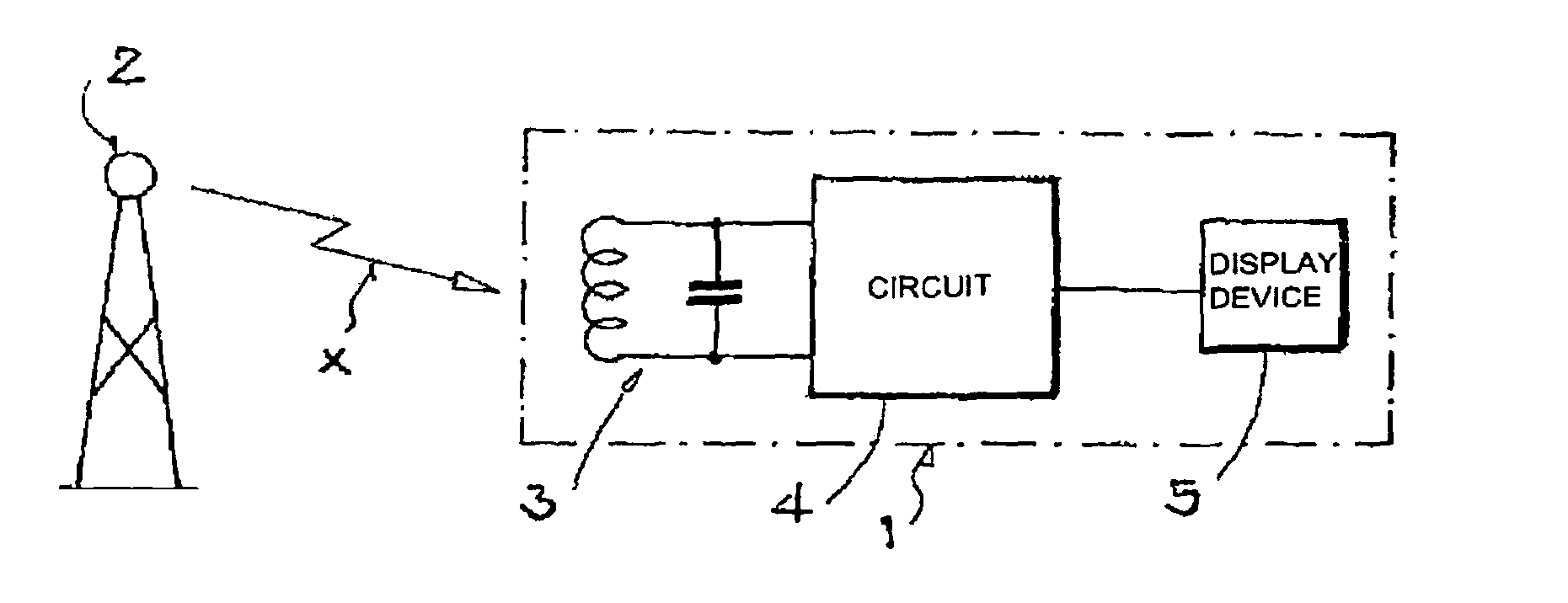
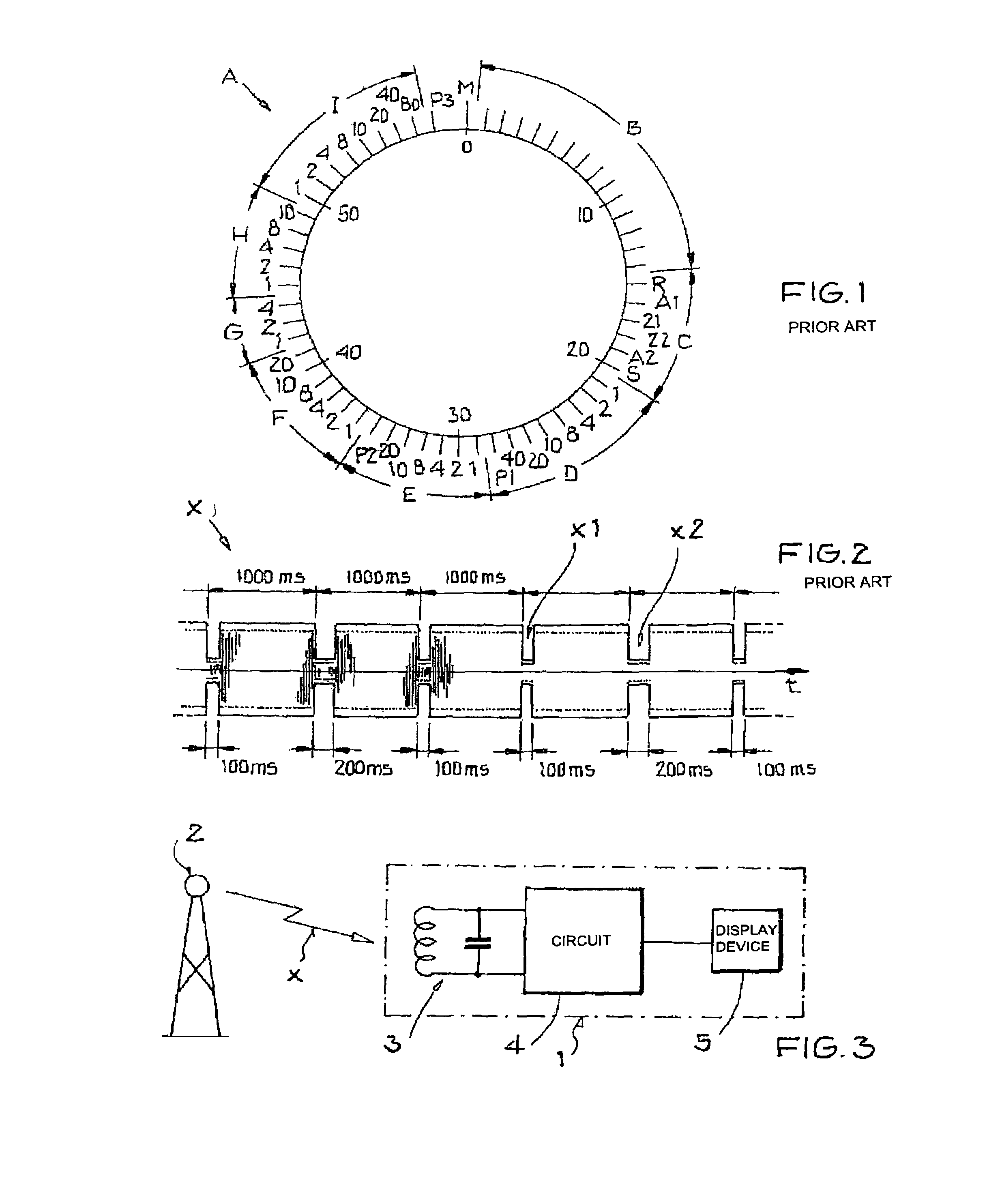
[0032]FIG. 3 shows a greatly simplified schematic block diagram of a radio clock 1. The radio clock 1 receives time signals X (see FIGS. 1, 2) from a time signal transmitter 2. To this end, the radio clock 1 has a receiving antenna 3, which is followed by a circuit arrangement 4 which is explained in detail below with reference to FIG. 4. The radio clock 1 also has, connected after the circuit arrangement 4, at least one display device 5, by which the time information obtained from the time signal X is displayed for a user of the radio clock 1.

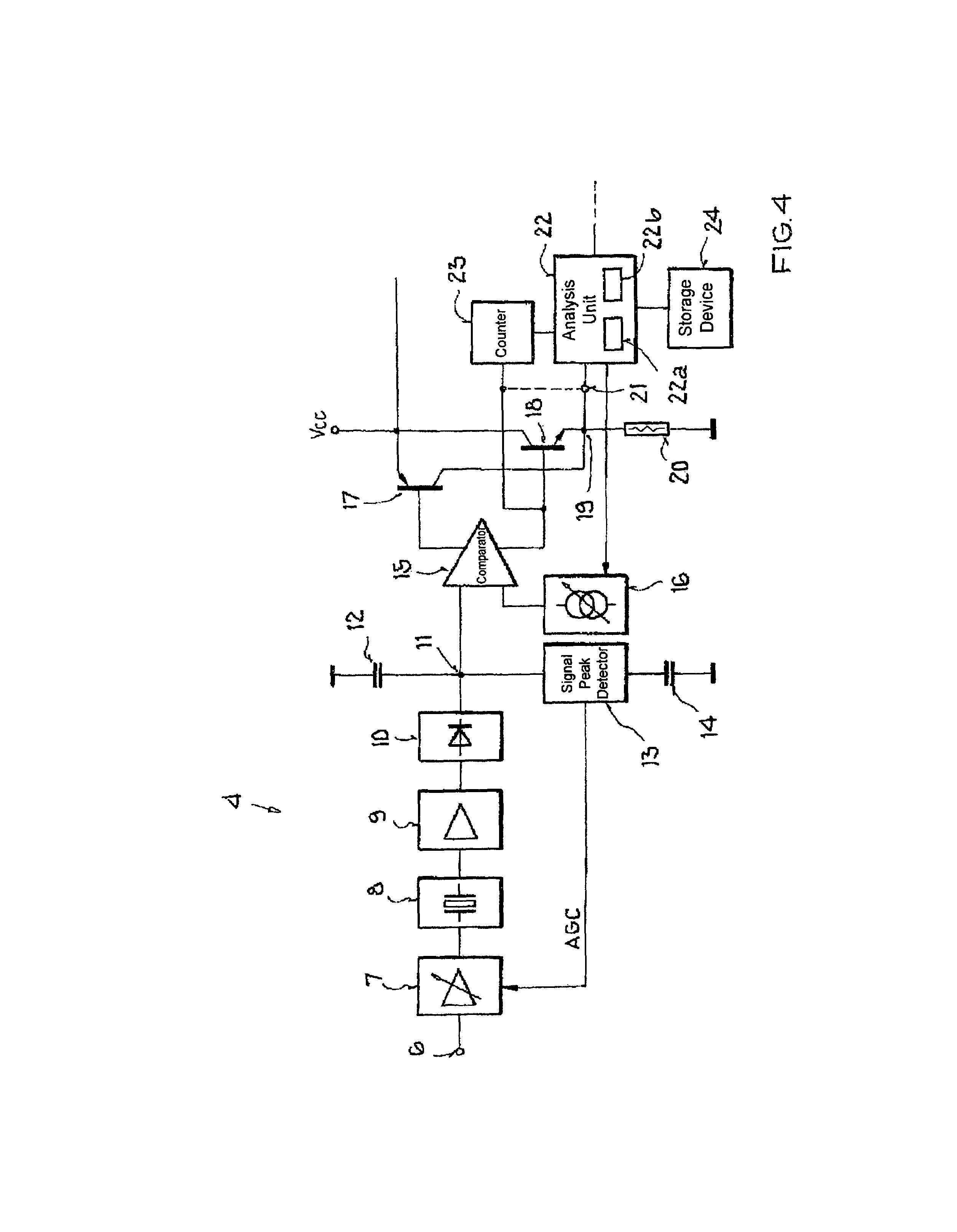
[0033]FIG. 4 shows a more detailed schematic block diagram of the inventive circuit arrangement 4 from FIG. 3, which is designed to receive and process the time signal X (FIG. 3) of the German transmitter DCF-77. The circuit arrangement 4 has, firstly, an input 6 for the received time signal X, which is present here with a typical signal strength of approximately 0.5 μV. The input 6 is connected to a regulating amplifier 7 in order to amplify ...


PUM


Abstract

A method for extracting time information from a received, amplitude-modulated time signal is provided. The method provides that the time signal is demodulated, the analog signal thus obtained is digitized by a comparator, and the digital signal thus obtained is analyzed to extract the time information. In addition, a characteristic value of the time duration of at least one signal phase of a specific signal level of the digital signal is compared to a target value, and a comparator threshold of the comparator is altered as a function of a result of the comparison such that the time duration of at least the applicable signal phase of the digital signal approaches the target value. In this way, an improved system sensitivity is achieved according to the invention in a receiver for receiving time signals. In particular, the frequency of occurrence of errors due to misreading of pulse lengths is reduced here, and distorted received signals are better detected as being distorted on account of their temporal deviation from the applicable target value. In addition, compensation of manufacturing tolerances of the various components in the described circuit arrangement is possible.

Description

[0001]This nonprovisional application claims priority under 35 U.S.C. §119(a) on German Patent Application No. DE 10 2005 056 483, which was filed in Germany on Nov. 26, 2005, and which is herein incorporated by reference.BACKGROUND OF THE INVENTION[0002]1. Field of the Invention[0003]The present invention relates to a method for extracting time information from a received, amplitude-modulated time signal, wherein the time signal is demodulated, the analog signal thus obtained is digitized by a comparator, and the digital signal thus obtained is analyzed to extract the time information.[0004]The present invention also relates to a circuit arrangement for receiving and extracting time information from amplitude-modulated time signals transmitted by a time signal transmitter, in particular for carrying out the inventive method, having a demodulator for demodulating the time signal and generating an analog signal from the time signal, having a comparator for digitizing the analog signa...

Claims


Application Information

Patent Timeline
Patent Type & Authority Patents(United States)
IPC IPC(8): H03D1/00H04L27/06G04G5/00G04R20/10
CPCG04C11/02G04G5/002G04G7/02H03K5/05H03K5/082H04L25/063G04R20/10H03M1/182
Inventor HAEFNER, HORST
Owner ATMEL CORP
Why Eureka
Try Eureka