Magnetic head slider manufacturing method
a manufacturing method and slider technology, applied in the direction of manufacturing tools, maintaining head carrier alignment, instruments, etc., can solve the problems of unstable recording magnetization, difficult to have higher density, and magnet poles repel each other, and achieve high precision. high
- Summary
- Abstract
- Description
- Claims
- Application Information
AI Technical Summary
Benefits of technology
Problems solved by technology
Method used
Image
Examples
first embodiment
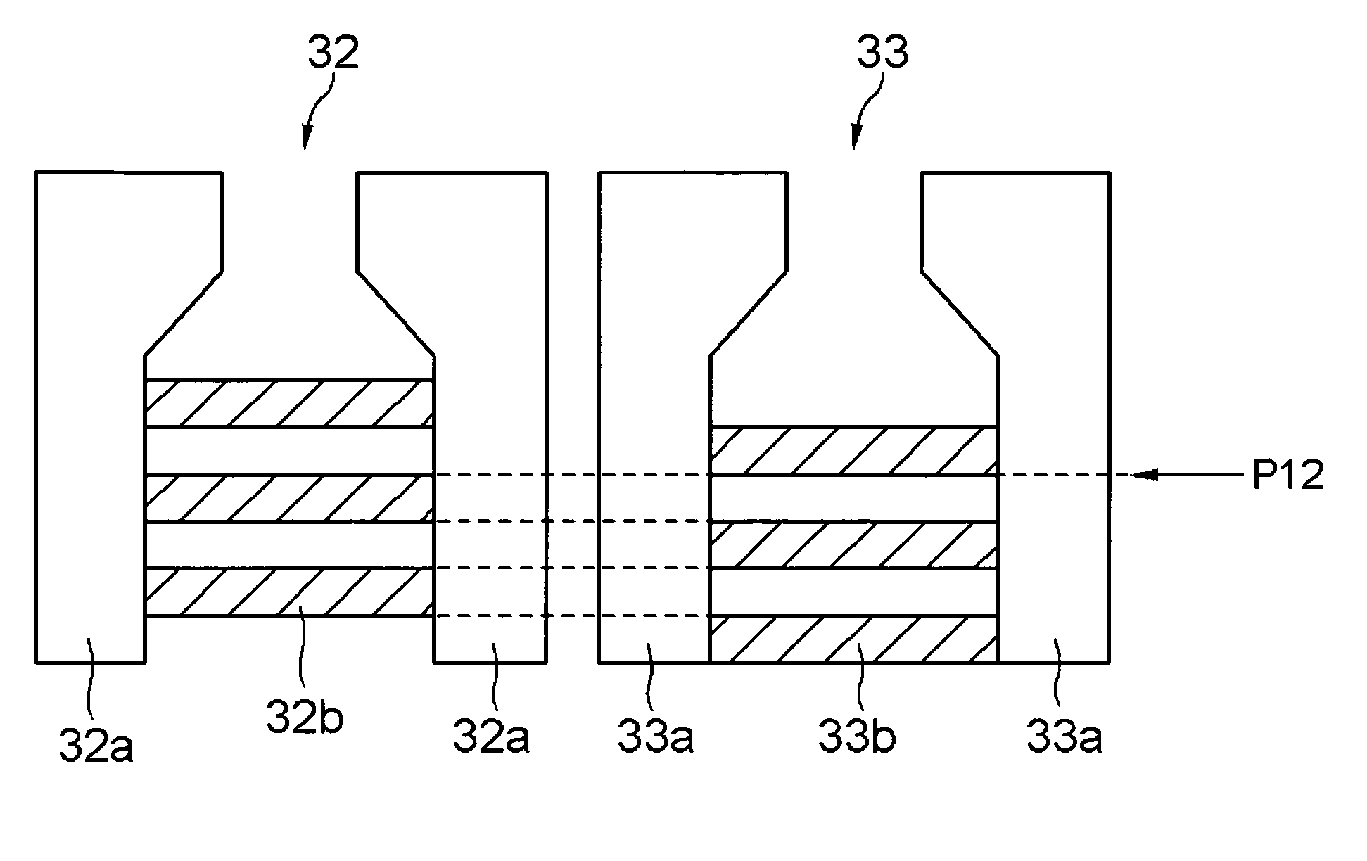
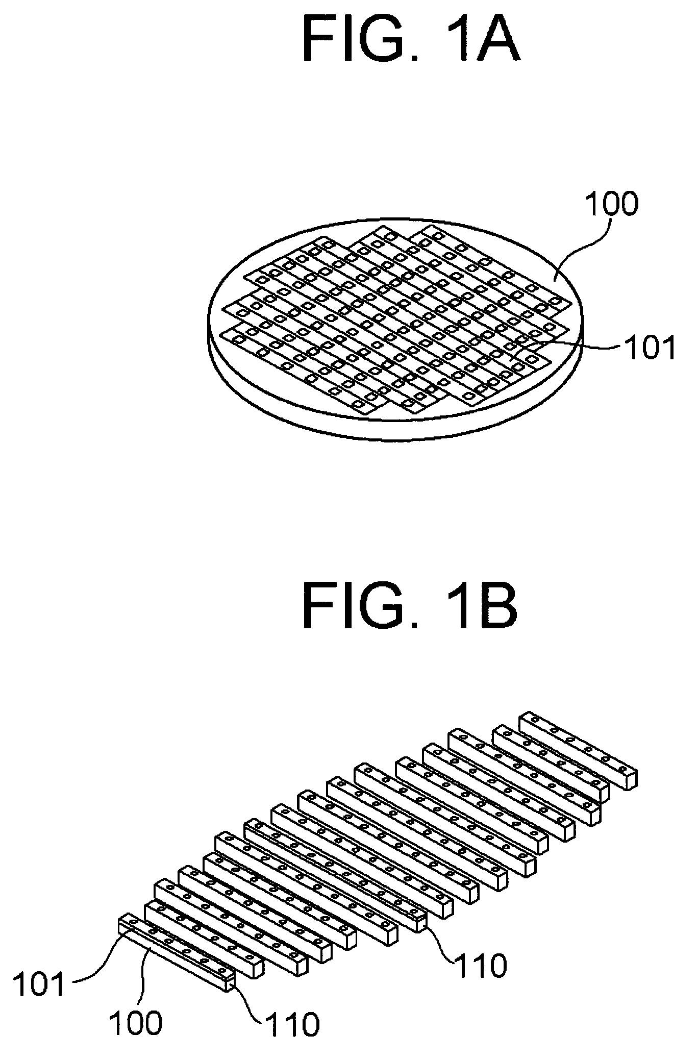
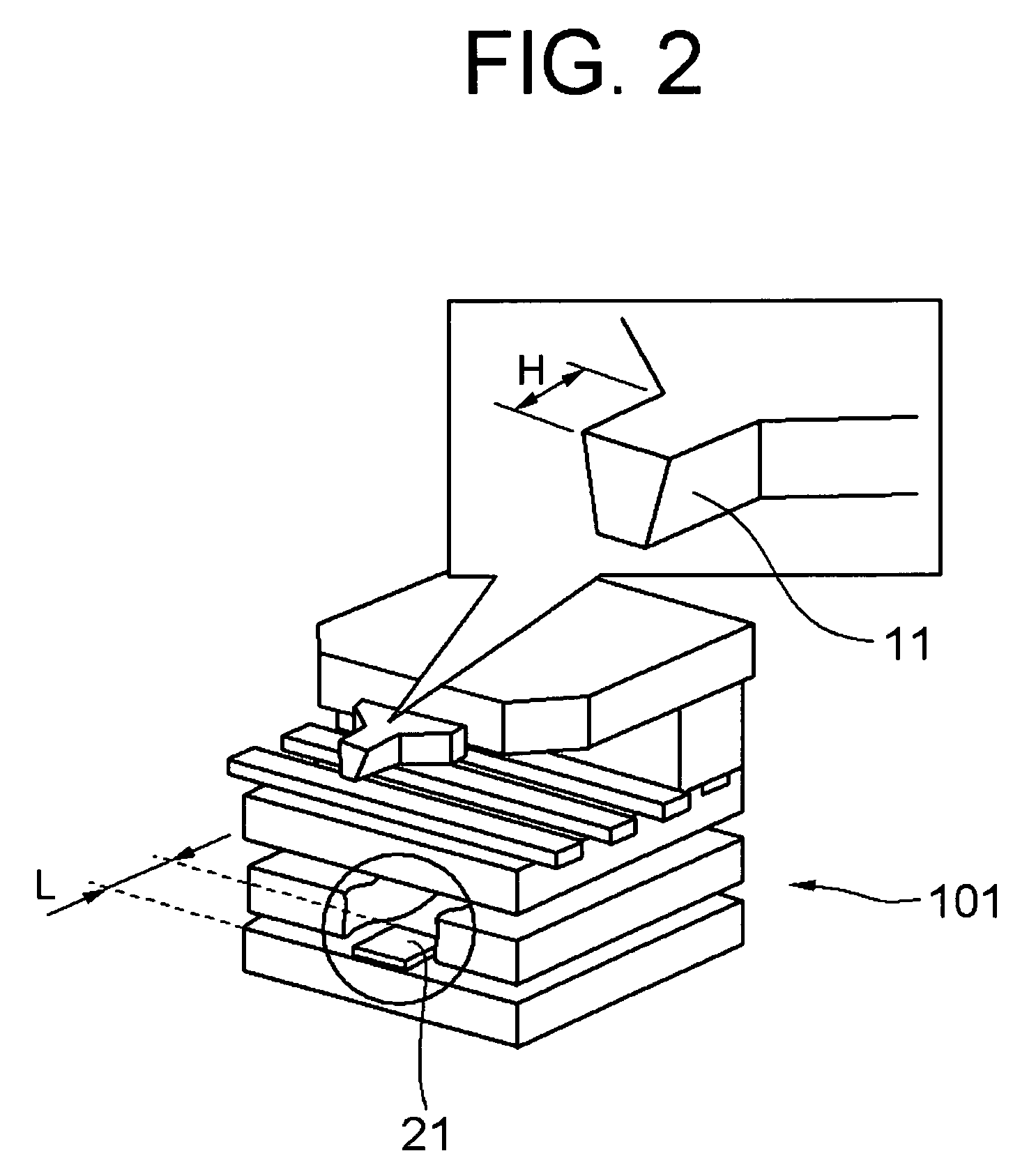
[0074]A first embodiment of the present invention will be described by referring to FIG. 1-FIG. 22. FIG. 1 is an illustration showing a state where magnetic heads are stacked on a substrate. FIG. 2 and FIG. 3 are illustrations showing the laminated structure of the magnetic head part. FIG. 4 and FIG. 5 are illustrations showing the structure of a reproducing-element forming layer and a recording-element forming layer. FIG. 6-FIG. 12 are illustrations showing the structure of the reproducing-element forming layer and the recording-element forming layer, and a state at the time of polishing. FIG. 13 is an illustration showing a state of measurements, when polishing a magnetic head slider. FIG. 14 shows illustrations of states at the time of adjusting polishing angle for the magnetic head slider. FIG. 15 is an illustration showing a state when cutting out magnetic head sliders from a bar block. FIG. 16 shows illustrations for describing a relation between the thickness of the sensor an...
second embodiment
[0106]Next, a second embodiment of the present invention will be described by referring to FIG. 23-FIG. 29. In this embodiment, basically, magnetic head sliders are manufactured by the magnetic head slider manufacturing method described above. However, the second embodiment further includes a step for adjusting the lengths of the recording element 11 and the reproducing element 21 with still higher precision. The step added to the first embodiment will be described in detail hereinafter.
[0107]First, in the stacked-layer forming step of the second embodiment, a pair of polishing-end detecting sensors having the same structure as the above-described recording-element polish amount detecting sensor 12 is formed on the same layer as that of the recording element 11 or on another layer. The recording-element polish amount detecting sensor 12 and the reproducing-element polish amount detecting sensor 22 may also be used as a pair of polishing-end detecting sensors. However, described in t...
PUM
| Property | Measurement | Unit |
|---|---|---|
| length | aaaaa | aaaaa |
| angle | aaaaa | aaaaa |
| polishing angle | aaaaa | aaaaa |
Abstract
Description
Claims
Application Information
 - R&D
- Intellectual Property
- Life Sciences
- Materials
- Tech Scout
- Unparalleled Data Quality
- Higher Quality Content
- 60% Fewer Hallucinations
Browse by: Latest US Patents, China's latest patents, Technical Efficacy Thesaurus, Application Domain, Technology Topic, Popular Technical Reports.
© 2025 PatSnap. All rights reserved.Legal|Privacy policy|Modern Slavery Act Transparency Statement|Sitemap|About US| Contact US: help@patsnap.com


