Blow molding machine with air conditioning

a blow molding machine and air conditioning technology, which is applied in the field of blow molding machines with air conditioning, can solve the problems of deteriorating working environment, increasing temperature affecting the economic logic of this approach, so as to prevent the deterioration of the work environment in the factory building, stable production, and constant flow rate

Inactive Publication Date: 2012-05-01
TOYO SEIKAN KAISHA LTD
View PDF10 Cites 8 Cited by
  • Summary
  • Abstract
  • Description
  • Claims
  • Application Information

AI Technical Summary

Benefits of technology

[0028]In the blow molding machine with air conditioning of the present invention, filtered / cooled clean air spreads within the factory building and is then recirculated to the heating zone and the blow zone. Therefore, not only the temperature in the factory building but also the atmosphere temperatures in the heating zone and the blow zone can be kept constant through repeated circulation of this clean air. The high-pressure air used during biaxial stretch blow molding of the preforms comprises a substantial amount of oxygen. Therefore, it is also possible to keep constant the temperature in the factory building, as well as the atmosphere temperatures in the heating zone and the blow zone, while keeping introduction of outside air to a minimum, by appropriately suctioning the high-pressure air by way of suction means such as a fan, filtering / cooling the high-pressure air, alongside the heated air of the heating zone and the recirculated clean air, and re-discharging the air into the factory building. The heated air of the heating zone is appropriately captured by suction means such as a fan. As a result, this allows preventing the work environment in the factory building from deteriorating on account of rising temperature.
[0029]In the blow molding machine with air conditioning of the present invention, the atmosphere temperatures in the blow zone and the heating zone can be kept constant by returning again, to the blow zone, some or all the clean air suctioned from the heating zone, filtered and adjusted to constant temperature and constant flow rate, in a continuous flow of clean air from the blow zone to the heating zone. As a result, bottles can be produced stably, with stable measured values of the final-shape bottles, even if the outside air temperature (temperature in the building) fluctuates. The air returned to the blow zone becomes high-temperature air by passing through the heating zone, is suctioned by a suction port, exchanges heat with the first cooling means and is further pressure-fed by the air-blowing means, becoming low-temperature air that is re-used. On the other hand, the remaining low-temperature air not being reused is discharged into the building. This allows managing both temperature and pressure in the building in which the blow molding machine is installed, and has the effect of lowering as a result the total running costs incurred in, for instance, temperature control in the building and temperature control in the blow zone and the heating zone. The air flowing out of the blowout port of the blow zone is filtered clean air that is continuously supplied from the blow zone to the heating zone. This allows as a result keeping both of the blow zone and the heating zone in appropriate clean condition.
[0030]The temperature of the air being returned to the blow zone is adjusted with high precision since it is adjusted through operation of the first cooling means and the second cooling means, or through operation of the air-blowing means, or by a suitable combination of these.

Problems solved by technology

The associated extra cost undermines the economic logic of this approach.
However, doing so necessitates filtering and air conditioning equipment, and so this approach is no different from the above-described one.
Discharging heater air into the factory building, however, causes the temperature in the factory building to rise, which deteriorates the working environment.

Method used


Image

  • Blow molding machine with air conditioning
  • Blow molding machine with air conditioning
  • Blow molding machine with air conditioning

Examples


Embodiment Construction

[0070]The present invention will be explained in more detail with reference to the following embodiments illustrated in the figures.

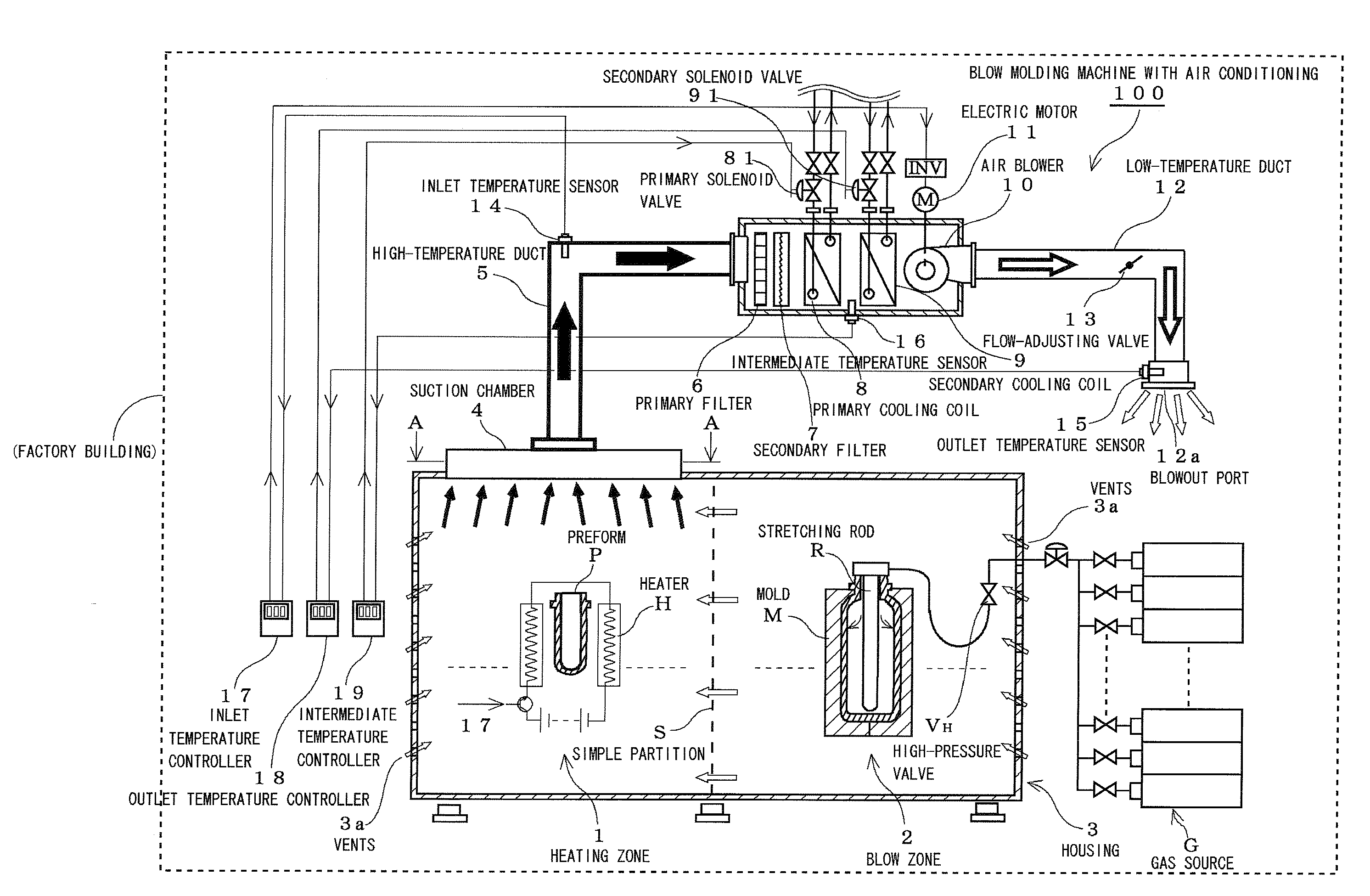
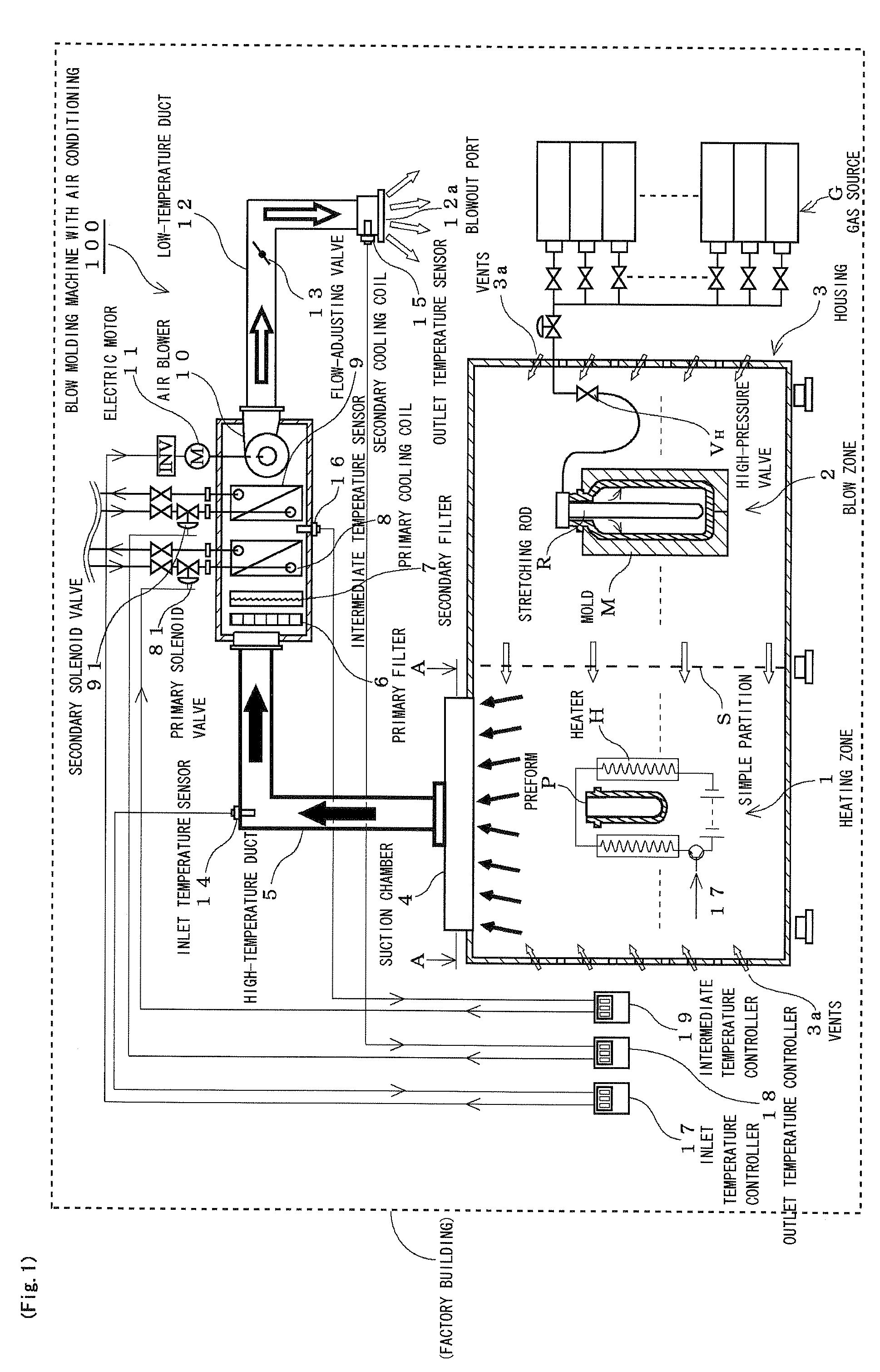
[0071]FIG. 1 is a schematic explanatory diagram illustrating a blow molding machine with air conditioning 100 of the present invention.

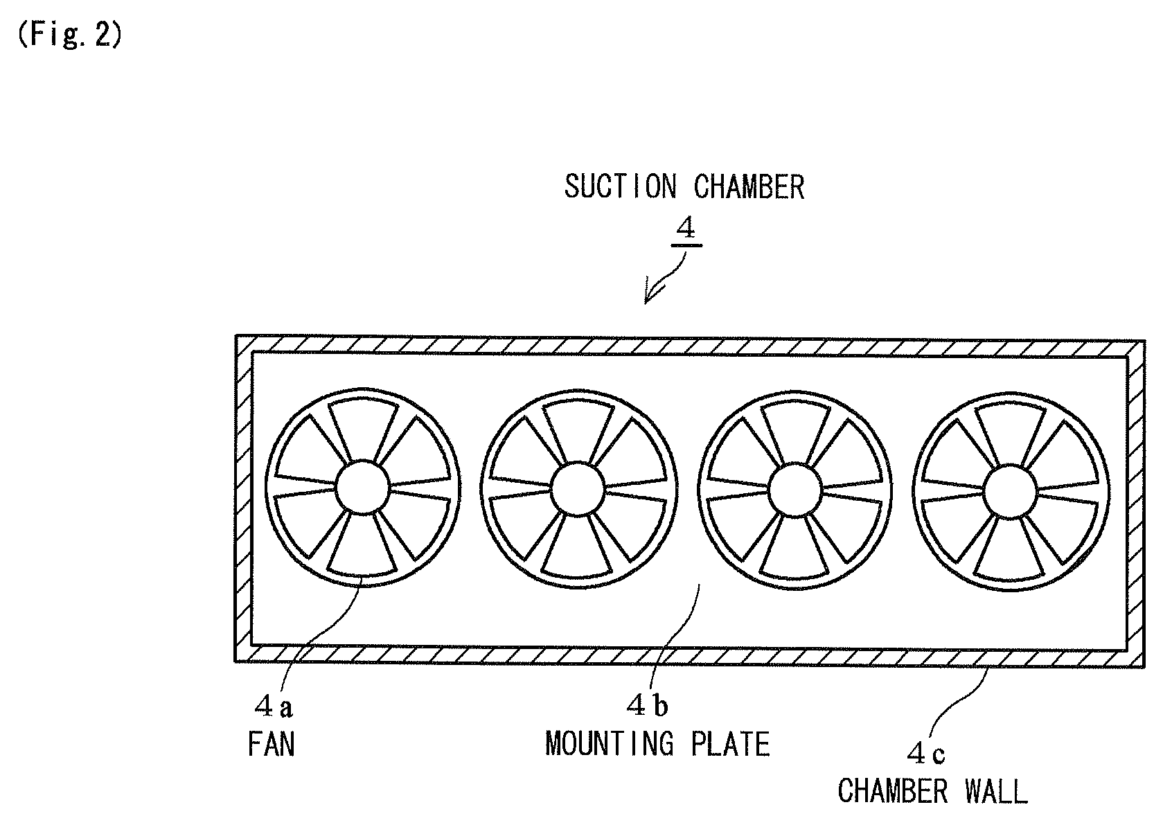
[0072]The blow molding machine with air conditioning 100 comprises a heating zone 1 where a preform P is pre-heated by a heater H; a blow zone 2 where the pre-heated preform P is set in a mold M and biaxial stretch blow molding is carried out using a stretching rod R and high-pressure air; a housing 3 covering the above zones; a suction chamber 4 that suctions heated air from the heating zone 1; a high-temperature duct 5 through which there flows the heated air suctioned by the suction chamber 4; a coarse primary filter 6 that filters the heated air; a fine secondary filter 7 that filters the heated air; a primary cooling coil 8, as first cooling means, through which there flows cooling water that robs heat from the heat...


PUM

PropertyMeasurementUnit
temperatureaaaaaaaaaa

Abstract

A blow molding machine with air conditioning that while minimizing the introduction rate of outside air maintains constant temperature in a plant building and the interior of a blow molding machine and production of a bottle as a final configuration with stability in its measurement value. The machine is constructed so that air for biaxially stretching blow molding together with hot air of heating zone and internal air of a plant building is suctioned by suction chamber, filtered by primary filter and secondary filter into clean air, brought into heat exchange with primary cooling coil, fed under pressure by air blower and released through low-temperature duct into the interior of the plant building. Further, a housing on its side face is provided with vent to allow reflux of the clean air released into the interior of the plant building and flow into the heating zone and blow zone.

Description

TECHNICAL FIELD[0001]The present invention relates to a blow molding machine with air conditioning, and more particularly to a blow molding machine with air conditioning for biaxial stretch blow molding of bottles from preforms, in which the temperature in a factory building and the temperature in a blow molding machine are kept constant while keeping the introduction of outside air to a minimum, and in which bottles as the final shapes can be produced with stable measured values.BACKGROUND ART[0002]In food processing plants, food packaging manufacturing plants and the like, the interior of the factory building is kept at positive pressure by setting air pressure in the factory building to be higher than external pressure, with a view to preventing contamination of the factory building by outside germs. When introducing outside air (air outside the factory building) into the factory building, therefore, the air is introduced after being filtered to remove as many germs and the like ...

Claims


Application Information

Patent Timeline
Patent Type & Authority Patents(United States)
IPC IPC(8): B29C49/42B29C49/68
CPCB29C49/46B29C49/78B29C49/06B29C49/68B29C49/4284B29C2049/4673B29C2049/4679B29C2049/4697B29C2049/4632Y02P70/10B29C2049/023B29C2949/0715B29C2049/78675
Inventor MATSUSHITA, YOUSUKESAWANE, NOBORU
Owner TOYO SEIKAN KAISHA LTD
Why Eureka
Try Eureka