
Electric vehicle

a technology for electric vehicles and vehicles, applied in the direction of gas pressure propulsion mounting, electric devices, refrigeration components, etc., can solve the problems of only being able to coast the vehicle, unable to achieve sufficient running performance of the vehicle, and reducing the motor load factor, so as to achieve safe evacuation driving, prevent unnecessary stop driving, and enable safe evacuation driving

Inactive Publication Date: 2012-05-01
TOYOTA JIDOSHA KK
View PDF16 Cites 7 Cited by
  • Summary
  • Abstract
  • Description
  • Claims
  • Application Information

AI Technical Summary

Benefits of technology

The present invention provides an electric vehicle that can safely drive when an overcurrent is generated in one of the inverters that drive the wheels. The invention includes a plurality of inverters that are connected to a plurality of motors. When an overcurrent is detected in one of the inverters, the inverter selection unit selects either the inverter that is connected to the motor that generated the overcurrent or the inverter that is not connected to the motor. The inverter drive control unit then drives only the selected inverter, effectively preventing damage to the motor. The invention also includes a planetary gear mechanism and an engine to provide power to the wheels. The invention can effectively evacuate the vehicle in case of an overcurrent and ensure safe driving.

Problems solved by technology

Because the generation of the overcurrent is successively repeated in the inverter when one of the inverters is broken, the motor load factor might gradually decrease even if the driving of the inverters is resumed, until, ultimately, sufficient running performance of the vehicle might not be obtained.
Therefore, when the overcurrent is generated in the inverter, a driver might only be able to coast the vehicle, even if the driver only attempts to drive the vehicle to the side of a road or to, for example, an automobile repair shop.

Method used


Image

  • Electric vehicle
  • Electric vehicle
  • Electric vehicle

Examples


Embodiment Construction

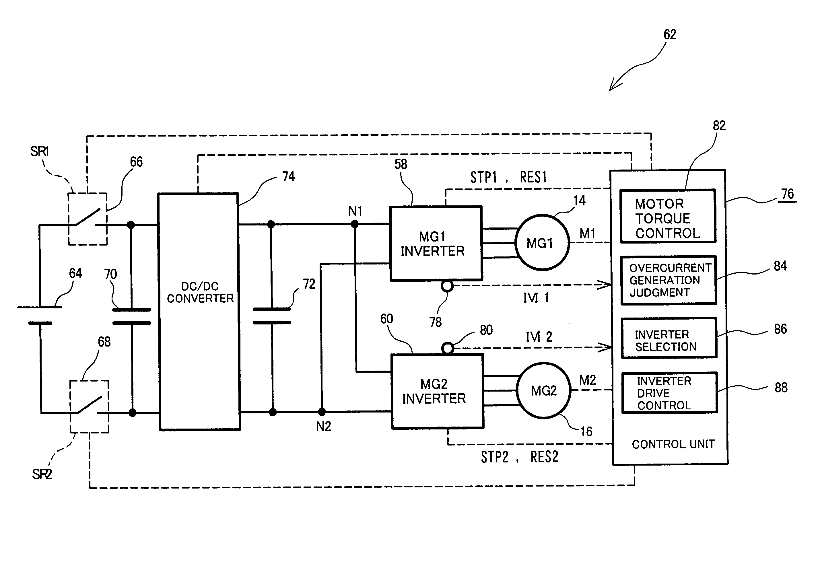
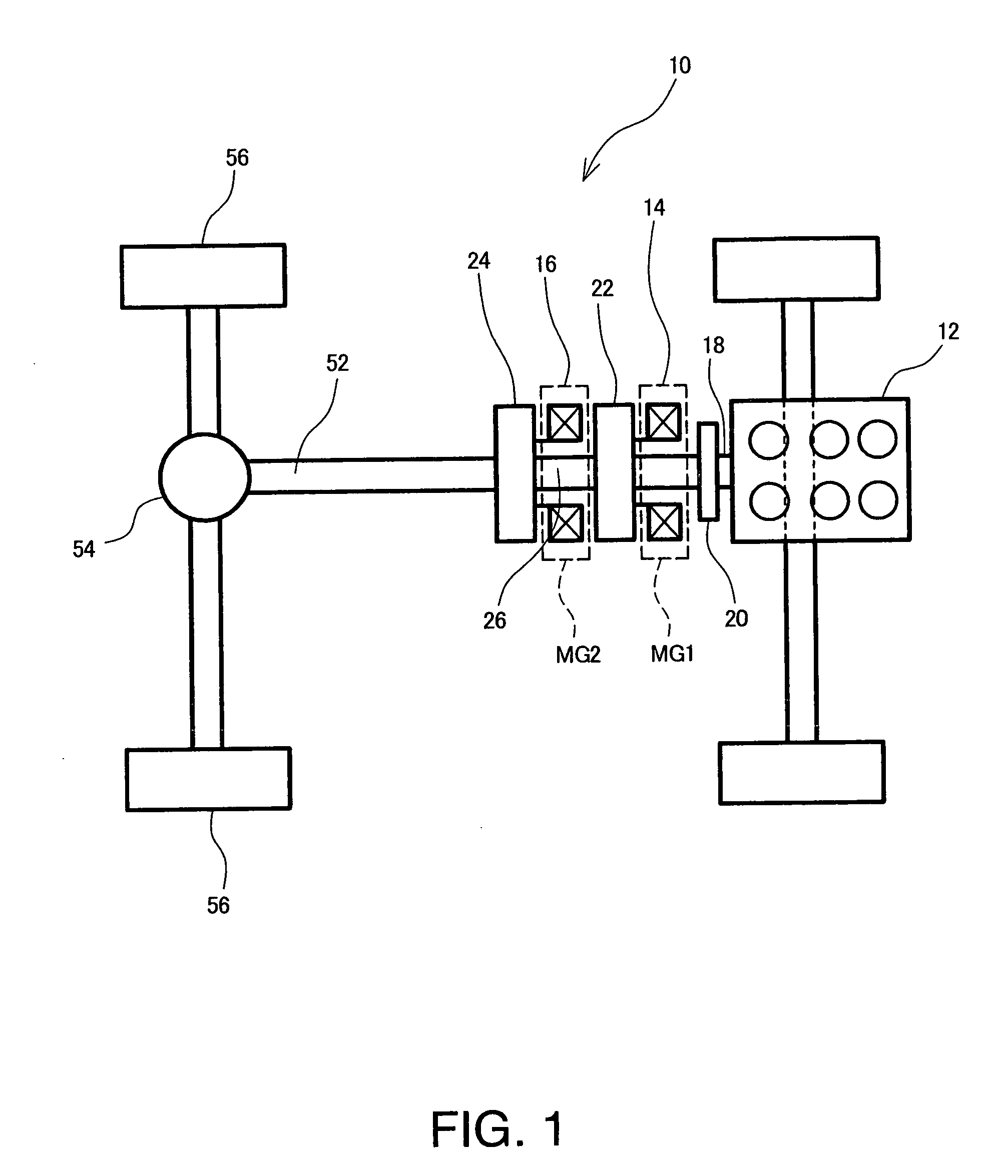
[0024]An embodiment according to the present invention will hereinafter be described in detail with reference to the drawings. FIG. 1 to FIG. 7 show one example of an embodiment according to the present invention. FIG. 1 is a schematic diagram of a hybrid vehicle 10, which is the electric vehicle of the present embodiment. The hybrid vehicle 10 is an FR vehicle which is a front engine rear-wheel-drive vehicle. The hybrid vehicle 10 includes an engine 12, a generator (MG1) 14 which is a first motor generator, and a travel motor (MG2) 16 which is a second motor generator. The generator 14 and the travel motor 16 correspond to the motors recited in claims.

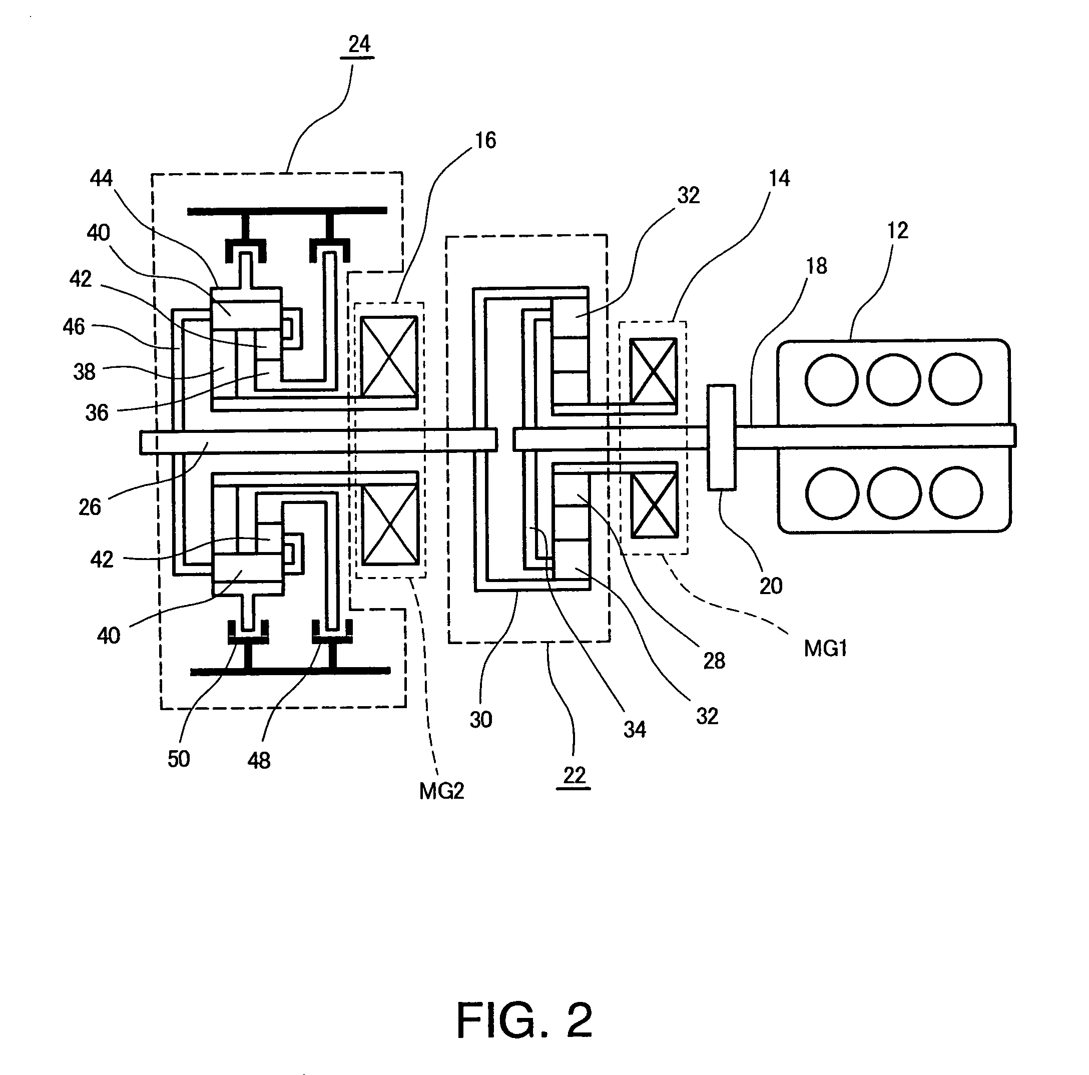
[0025]Furthermore, in the hybrid vehicle 10, a power divider 22 is coupled to a crank shaft of the engine 12 via a damper 20, and a rotary shaft of the generator 14 and an output shaft 26 of a reduction gear unit 24 with a two-speed transmission mechanism are coupled to the power divider 22. Further, a rotary shaft of the travel motor...


PUM


Abstract

An electric vehicle includes a control unit having overcurrent generation judgment unit, inverter selection unit, and inverter drive control unit. The overcurrent generation judgment unit judges whether an overcurrent is generated in an inverter for generation or an inverter for travel. When an overcurrent is generated in one of the inverters, the inverter selection unit selects the other inverter to be driven. The inverter drive control unit stops the driving of the one inverter and drives the other inverter to drive a travel motor or a generator.

Description

TECHNICAL FIELD[0001]The present invention relates to an electric vehicle including a plurality of inverters which are connected to a plurality of motors to drive wheels and which are connected in parallel to a DC power source.TECHNICAL BACKGROUND[0002]It has heretofore been known that, in an electric vehicle such as an electric automobile or a hybrid car equipped with a motor, an inverter and a motor control unit are provided between the motor and a power supply unit, and a motor current which is a driving signal is sent to the motor by the inverter to drive the motor. The inverter converts DC power from the power supply unit into an alternating current in accordance with a torque command value, and sends the resultant motor current to the motor. Further, the motor control unit sends, to the inverter, a control signal for generating the motor current.[0003]As one such electric vehicle, there has heretofore been a hybrid vehicle including a control unit, and a first motor generator ...

Claims


Application Information

Patent Timeline
Patent Type & Authority Patents(United States)
IPC IPC(8): H02K11/00B60L50/16
CPCB60L3/003B60L3/0092B60L11/123B60L11/14B60W10/08B60W30/1843H02P29/022B60K6/445B60K1/02Y02T10/7077B60L2240/425B60W20/00B60W2510/087Y02T10/6217Y02T10/6239Y02T10/642B60K6/48B60K2006/268B60K2006/4833B60L50/16B60L50/61H02P29/032Y02T10/62Y02T10/64Y02T10/70Y02T10/7072B60W10/30B60W20/15
Inventor KISHIMOTO, TAKESHI
Owner TOYOTA JIDOSHA KK
Learn More