
Front electronic equipment system with a LIN-subbus

a technology of electronic equipment and subbus, which is applied in the direction of process and machine control, program control, electric programme control, etc., can solve the problems of increasing the mass, and increasing the number of circuits, so as to reduce the noise emitted and the effect of easy handling of functions changes

Inactive Publication Date: 2012-05-01
YAZAKI CORP
View PDF51 Cites 5 Cited by
  • Summary
  • Abstract
  • Description
  • Claims
  • Application Information

AI Technical Summary

Benefits of technology

This configuration results in a simplified, lightweight, and compact system that easily handles changes in auxiliary equipment functions, reduces noise, and lowers development complexity, while maintaining necessary communication speed and reducing costs.

Problems solved by technology

Particularly, when functions of the front auxiliary equipments are increased, a number of circuits is increased and the wire harnesses become bulky to bring about an increase in mass thereof.
At the same time, the front ECU also becomes bulky to bring about an increase in mass (deterioration of fuel / running function) and a deterioration in mountability and also softwares mounted to the front ECU become bulky.
Further, the front ECU is mounted with a number of load drive devices (semiconductor switches or mechanical relays) and therefore, small-sized formation thereof is difficult and a problem of heat generation is also caused.
Further, when lamps, motors and the like in the auxiliary equipments are driven by PWM (Pulse Width Modulation) control, there also poses a problem of emitting noise from the wire harnesses to the lamps or motors.

Method used


Image

  • Front electronic equipment system with a LIN-subbus
  • Front electronic equipment system with a LIN-subbus
  • Front electronic equipment system with a LIN-subbus

Examples


Embodiment Construction

[0048]A detailed explanation will be given of embodiments of the invention in reference to the attached drawings as follows.

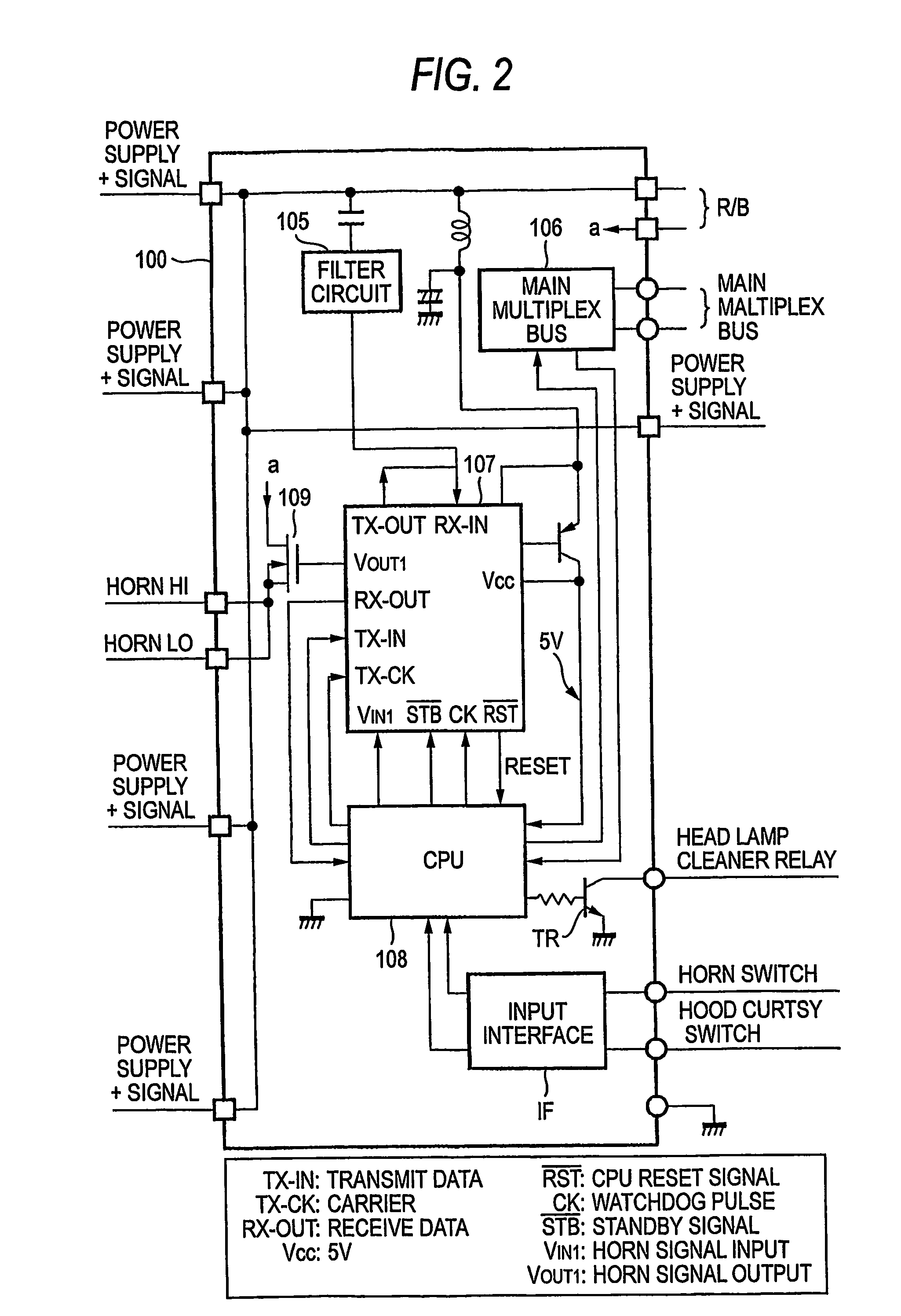
[0049]FIG. 3 is a functional block diagram showing the basic concept of an electronic connector according to an embodiment of the invention. An electronic connector 110 directly connected to a connector of a sensor 114 is provided with a communication portion 111, a control portion 112 and an I / O portion 113 mounted on an electronic board included therein. Also an electronic connector 120 directly connected to a switch SW124 is provided with a communication portion 121, a control portion 122 and an I / O portion 123 mounted on an electronic board included therein. An electronic connector 130 directly connected to a load (lamp, motor or the like) 134 is provided with a communication portion 131, a control portion 132 and a drive portion 133 mounted on an electronic board included therein. An electronic connector 140 directly connected to an auxiliary equipment mod...


PUM


Abstract

A front electronic equipment system includes a load electrical parts provided at a front portion of a vehicle, a front electrical control unit which receives a control signal for controlling the drive of the load electrical parts through a main bus line of the vehicle, and a drive control unit connected to the front electrical control unit through a sub bus line, converting the control signal into a drive signal, and driving the load electrical parts based on the drive signal. The front electrical control unit converts a communication protocol of the control signal from a communication protocol of the main bus line into a communication protocol of the sub bus line, and transmits the converted control signal received through the main bus line to the drive control unit through the sub bus line.

Description

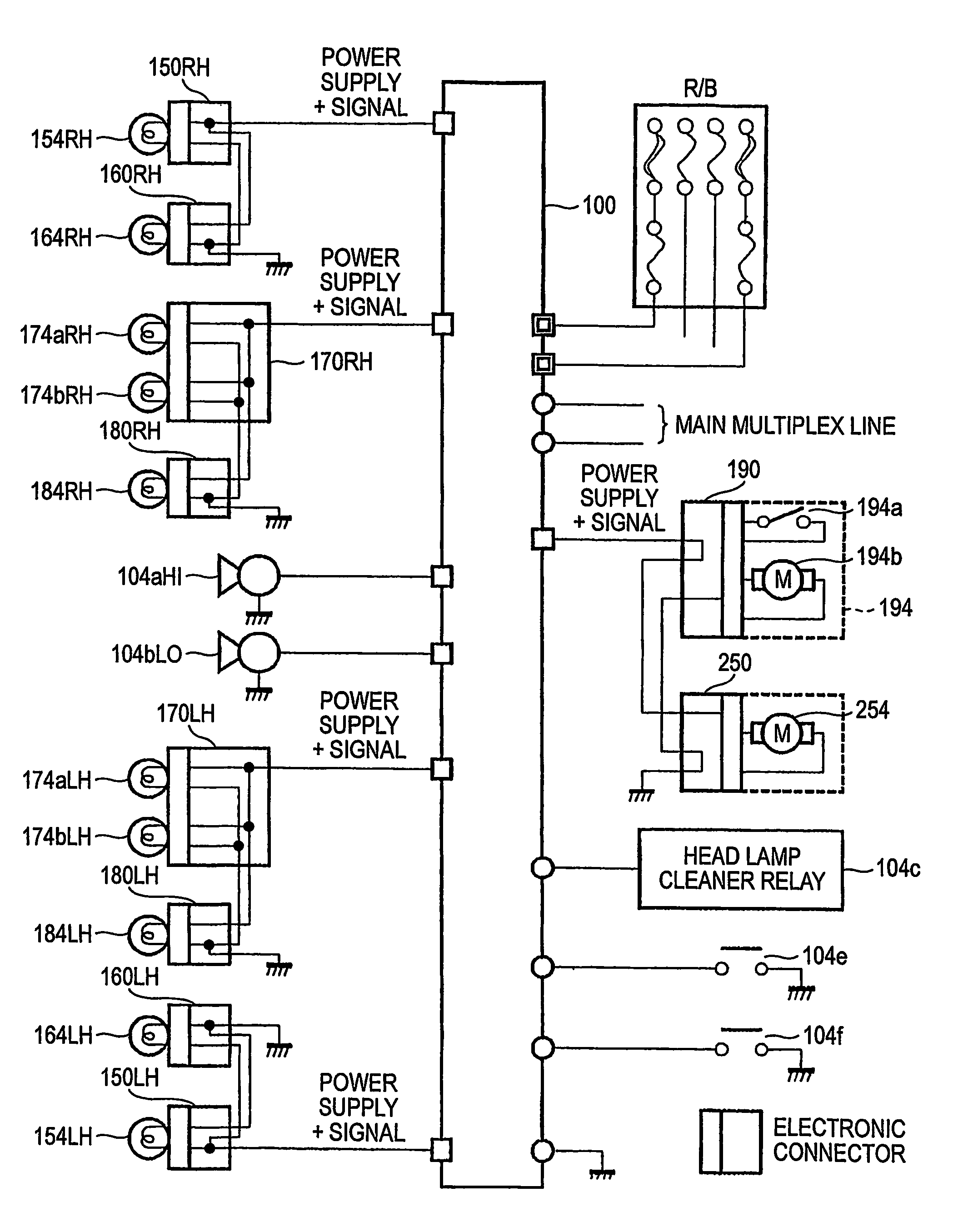
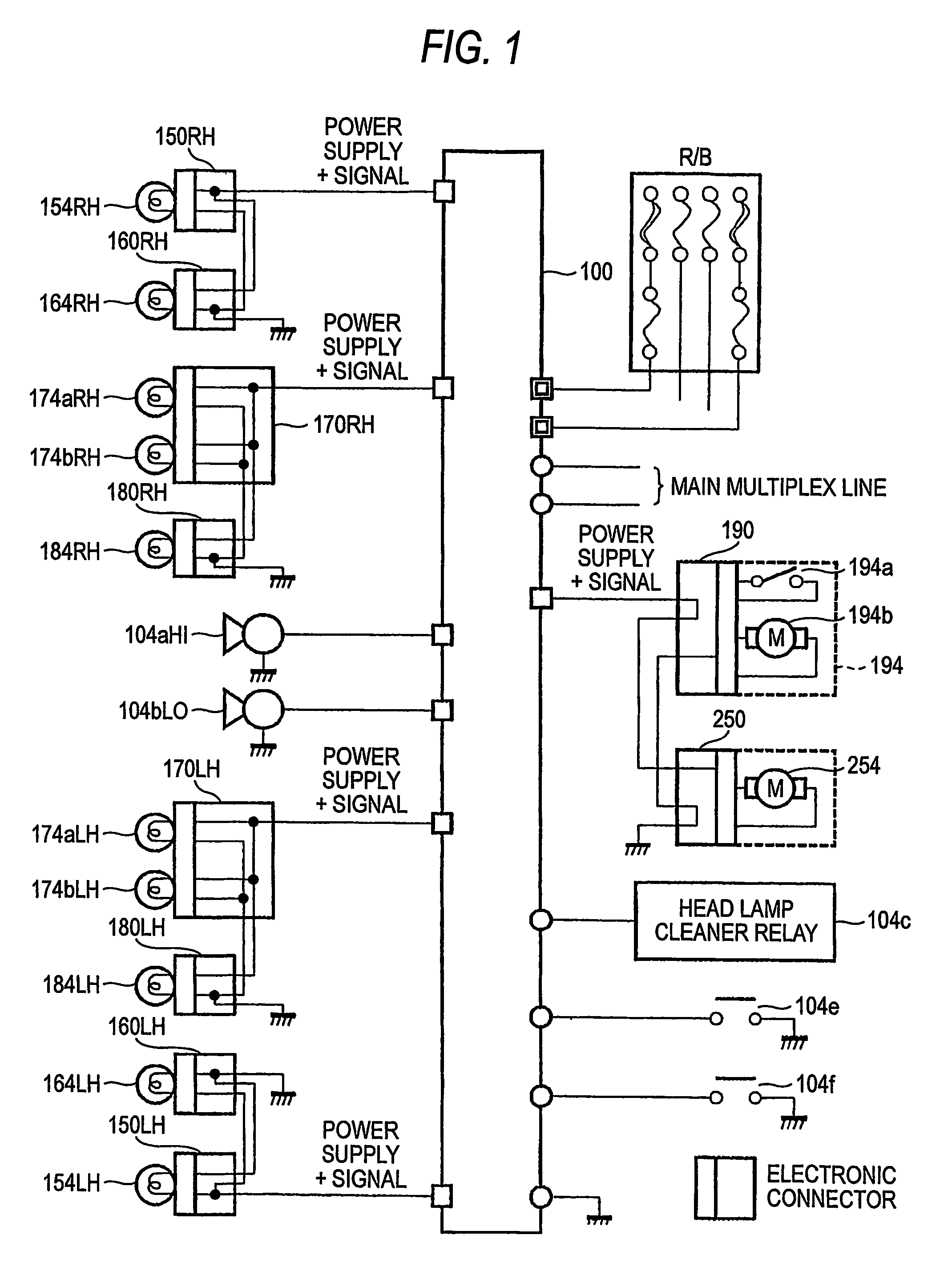
TECHNICAL FIELD[0001]The present invention relates to a front electronic equipment system for controlling front auxiliary equipments, such as a headlamp, a horn, a front washer and the like.BACKGROUND ART[0002]FIG. 11 is a circuit diagram showing a constitution example of a front electronic equipment system in a related art. A front ECU (Electronic Control Unit) 100 is connected with a power source line for supplying a power source from a battery, a main multiplexed line connected with a LAN (Local Area Network) for vehicle communicated by a protocol of CAN (Controller Area Network) or the like, various front auxiliary equipments, rear auxiliary equipments, sensors and switches.[0003]The front ECU 100 is connected with head lamps 154RH, 154LH, side marker lamps 184RH, 184LH, clearance lamps 174aRH, 174aLH, front fog lamps 164RH, 164LH, cornering lamps 174bRH, 174bLH, horns 104aHI, 104bLO, and a front washer motor 194b as front auxiliary equipments by wire harnesses. Further, the fro...

Claims


Application Information

Patent Timeline
Patent Type & Authority Patents(United States)
IPC IPC(8): G05B15/00B60R16/02B60Q1/00H04L12/00H04L12/40
CPCH04L12/403H04L12/4135H04L2012/40215H04L2012/40234H04L2012/40273
Inventor NAGASAWA, KAZUMIOZAKI, TOSHIAKISHIMIZU, NORIHITO
Owner YAZAKI CORP
Learn More