Crankcase breathing system

a breathing system and crankcase technology, applied in mechanical equipment, machines/engines, hoisting equipment, etc., can solve the problems of delayed oil pressure build-up, inability to prevent especially small oil drops, and considerable production effort for achieving high surface quality, etc., to achieve rapid oil pressure progression, improve the cooling of the vibration damper, and reduce the effect of vibration

Inactive Publication Date: 2012-05-08
AVL LIST GMBH
View PDF30 Cites 3 Cited by
  • Summary
  • Abstract
  • Description
  • Claims
  • Application Information

AI Technical Summary

Benefits of technology

[0040]It is especially advantageous when a vibration damper is rotationally connected with the hub part. In order to achieve sufficient cooling for the vibration damper, it can be provided with ventilating elements. It is further advantageous for improving cooling of the vibration damper when the hub part comprises at least one axial flow opening for cooling air. The coolant reaches the vibration damper via the flow openings in the hub part and flows supported by the ventilating elements between pulley and vibration damper radially to the outside, with the surface of the vibration damper being cooled.
[0041]In order to achieve a rapid oil pressure progression during cold starting it is advantageous when a control line which opens into the control chamber and is supplied with the contr...

Problems solved by technology

The entrainment of especially small oil drops still cannot be prevented in the case of especially high flow quantities.
Especially in the case of poly-V belt disks arranged in several steps...

Method used


Image

  • Crankcase breathing system
  • Crankcase breathing system
  • Crankcase breathing system

Examples


Embodiment Construction

[0072]Parts with the same function are provided with the same reference numeral.

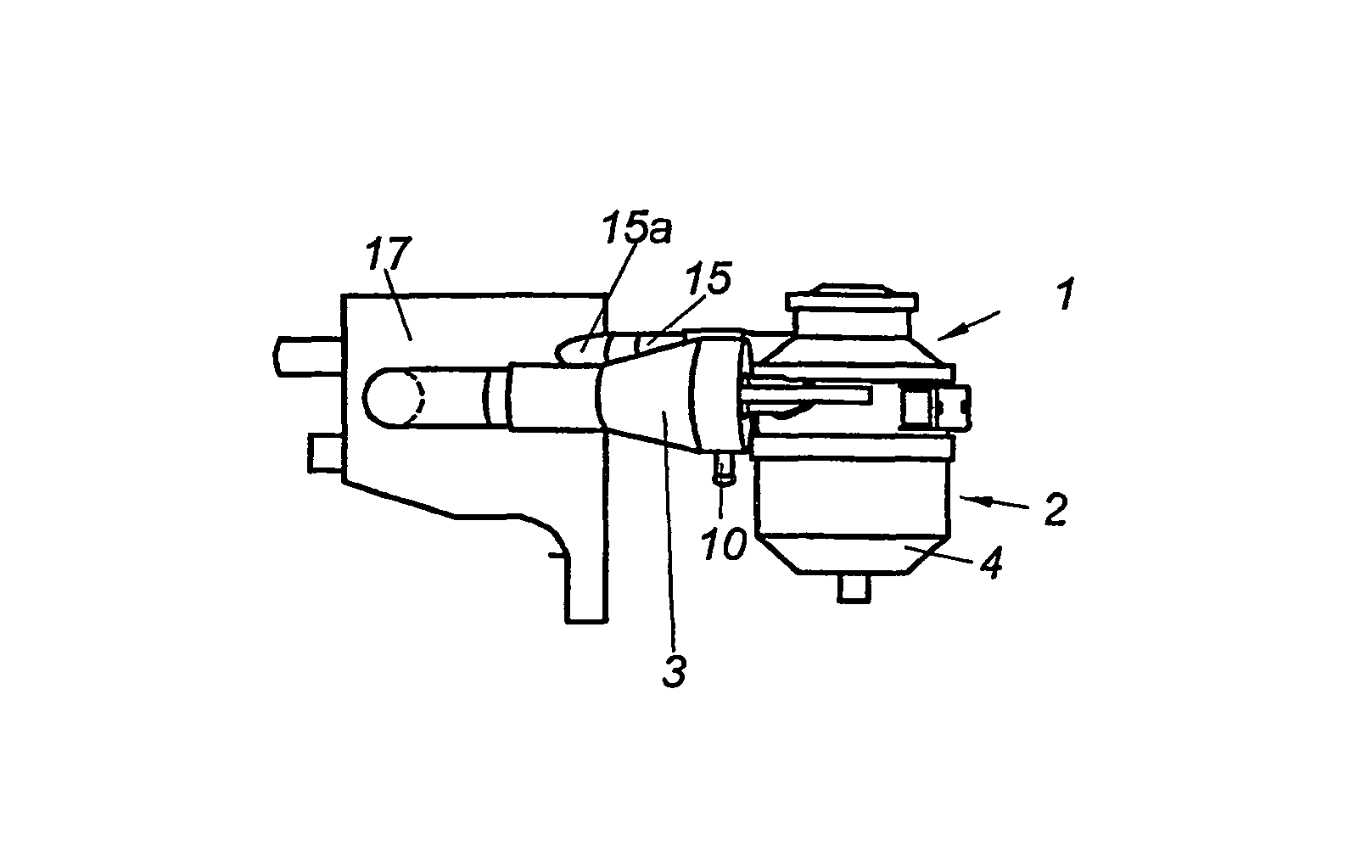
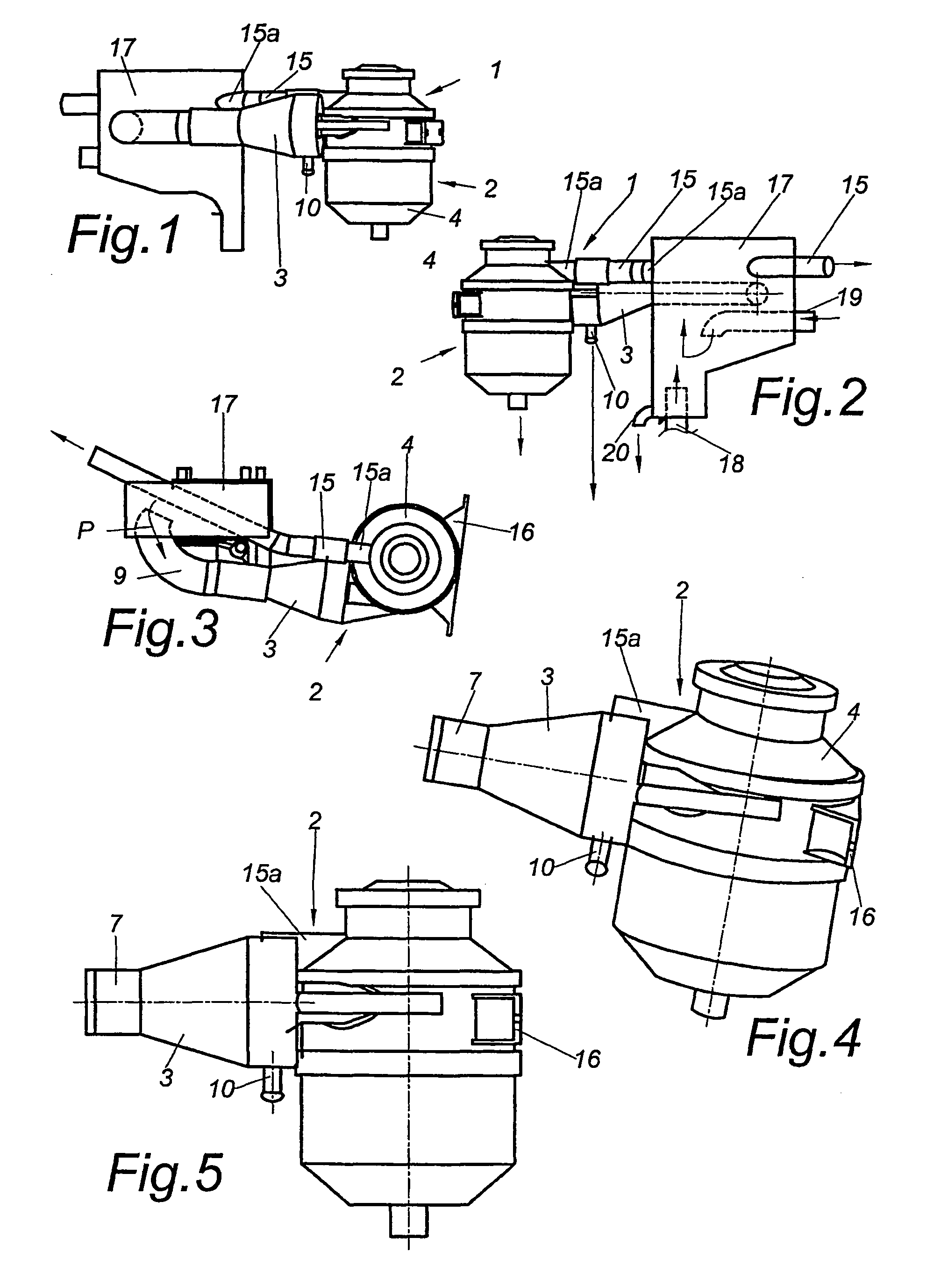
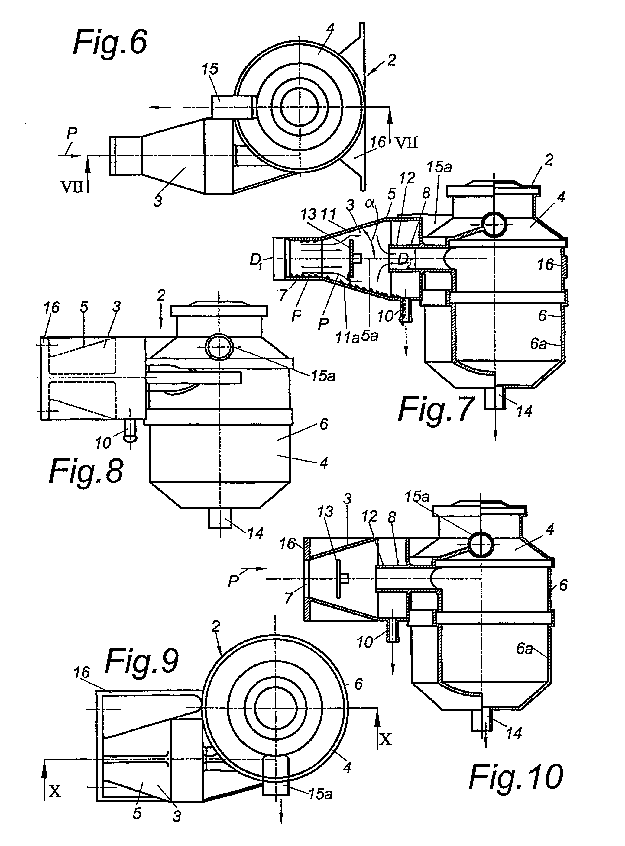
[0073]The crankcase breathing system 1 as shown in FIGS. 1 to 3 comprises a separator unit 2 which consists of a preliminary separator 3 and a main separator 4. The separator unit 2 is shown in detail in FIGS. 4 to 7. The housing 5 of the preliminary separator 3 and the housing 6 of the main separator 4 are arranged integrally, which thus allows cost-effective production. The main separator 4 can be arranged as a cyclone separator with integrated nonwoven separator and with a pressure control valve provided upstream of the gas outlet. Furthermore, the main separator 4 can also be arranged as a multi-cyclone separator or as an electric system.

[0074]The preliminary separator 3 comprises an inlet 7 for a crankcase breathing line 9 and an outlet 8 which opens tangentially into the main separator 4. An outlet opening 10 is arranged at the lowest point of housing 5 of preliminary separator 3, to which opening ...


PUM


Abstract

A crankcase breathing system (1) for an internal combustion engine includes at least one oil separating apparatus with a preliminary separator (3) and a main separator (4) arranged downstream of the same, with the preliminary separator (3) including a diffuser (11) between an inlet (7) and an outlet (8) which expands in the direction of flow. In order to achieve high separation rates in the simplest possible way it is provided that the preliminary separator (3) is arranged integrally with the main separator (4), with preferably the preliminary separator (3) and the main separator (4) forming a separator unit (2).

Description

BACKGROUND OF THE INVENTION[0001]1. Field of the Invention[0002]The invention relates to a crankcase breathing system for an internal combustion engine, comprising at least one oil separating apparatus with a preliminary separator and a main separator arranged downstream of the same, with the preliminary separator comprising a diffuser between an inlet and an outlet which expands in the direction of flow. The invention further relates to a liquid-cooled internal combustion engine with a crankcase for several cylinders with a cooling jacket about the cylinders in the crankcase, with individual cylinder heads with at least two cooling chambers arranged above one another in the cylinder head, with the cooling jacket of the crankcase and the bottom cooling chamber in the cylinder head being connected with each other via at least one, preferably at least four, transfer openings which are evenly distributed on the circumference of the cylinder. The invention also relates to a multi-part p...

Claims


Application Information

Patent Timeline
IPC IPC(8): F01P3/02
CPCF01M13/04F02F1/242F02F1/40F02F7/0007F02F7/007F01M1/02F01M2013/0072F01M2013/0422F01M2013/0494F01P2003/028F02F1/10
Inventor NAGENKOGL, GUNTHERROITHINGER, ROBERTPOSCHL, ROBERTALTENDORFER, HELMUTSCHRATTBAUER, ANDREASKNOLLMAYR, CHRISTOF
Owner AVL LIST GMBH
Why Eureka
Try Eureka