Variable displacement transmission pump control

a technology of transmission pump and variable displacement, which is applied in the direction of machines/engines, positive displacement liquid engines, liquid fuel engines, etc., can solve the problems of increasing cost and size, delay in hydraulic response time, and delay temperature sensitive, so as to reduce the loss of bleed circuit, reduce the loss of pump flow, and improve the hydraulic efficiency of the transmission

Active Publication Date: 2012-05-22
FORD GLOBAL TECH LLC
View PDF17 Cites 27 Cited by
  • Summary
  • Abstract
  • Description
  • Claims
  • Application Information

AI Technical Summary

Benefits of technology

[0011]The variable displacement pump is closed-loop controlled by incorporating a pressure sensor on a dedicated circuit from the main regulator. This arrangement decouples the flow control, i.e., pump displacement, from the variable pressure control, allowing optimized flow delivery, thereby improving the hydraulic efficiency of the transmission. The control eliminates need for a large bleed circuit to stabilize the pump.
[0012]Decreasing the pump flow by reducing the bleed circuit losses and improving the control of the pump increases the fuel economy of a vehicle powertrain that includes a transmission having the control system.
[0013]The variable displacement pump affects fuel economy by about two percent. The electro-hydraulic control potentially reduces the pumping flow by approximately 25 percent, which corresponds to a fuel economy improvement of about 0.5 percent.

Problems solved by technology

Such a valve body adds cost and size due to the many valve body layers, and it creates hydraulic response time delays due to the multiple stages from solenoid output to regulator valve input to regulator output, which must be controlled.
Further, these delays are temperature sensitive.
Conventional automatic transmissions use bleed flows to improve the hydraulic controls performance and repeatability, but these flows result in lost hydraulic power, which power loss is detrimental to fuel economy.
Variable displacement pump controls are indirectly controlled, which can introduce system instability and deliver a fluid flow rate that is much higher than needed by the transmission, further reducing fuel economy.
A conventional one-way-clutch is costly and creates internal drag in the transmission.

Method used


Image

  • Variable displacement transmission pump control
  • Variable displacement transmission pump control

Examples


Embodiment Construction

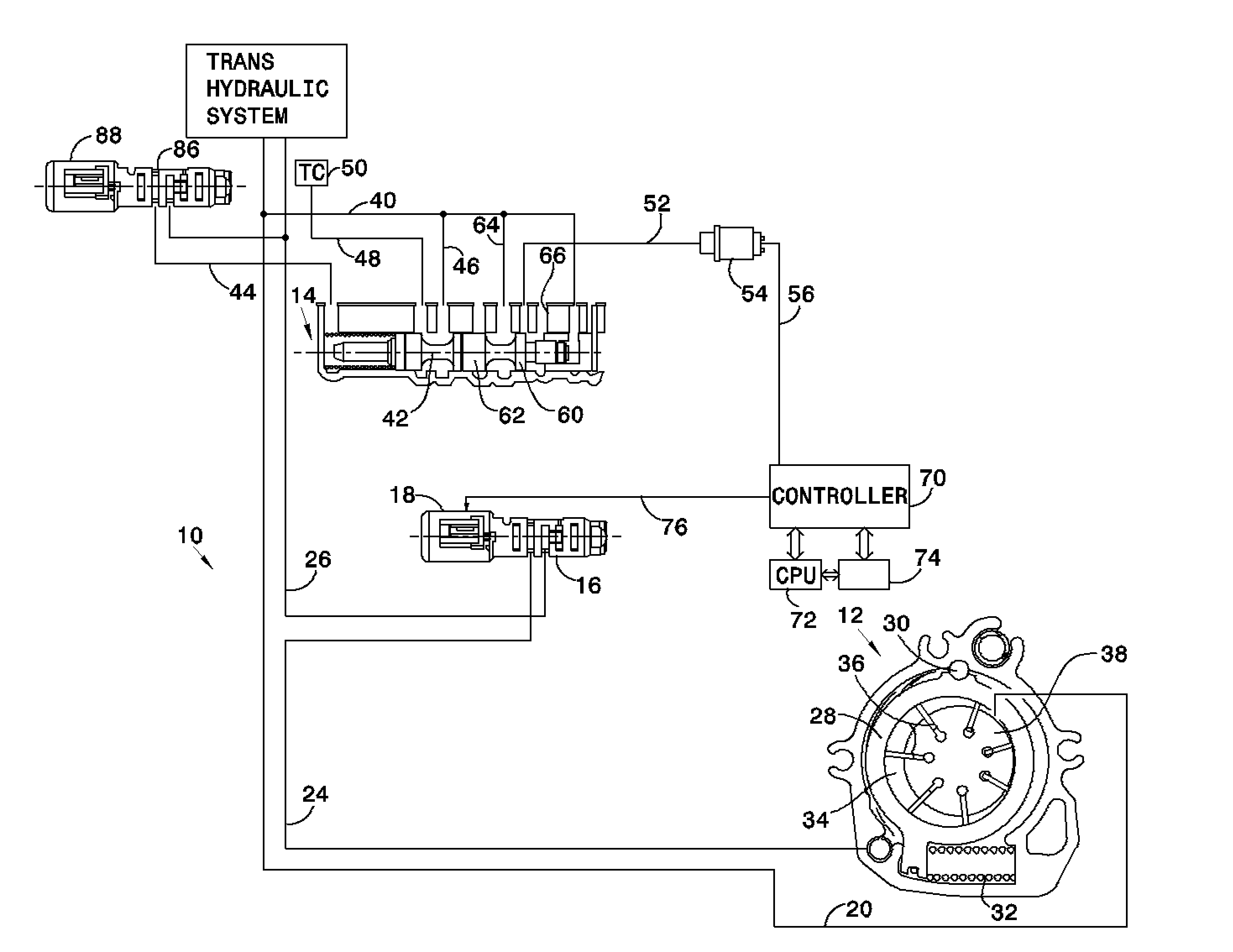
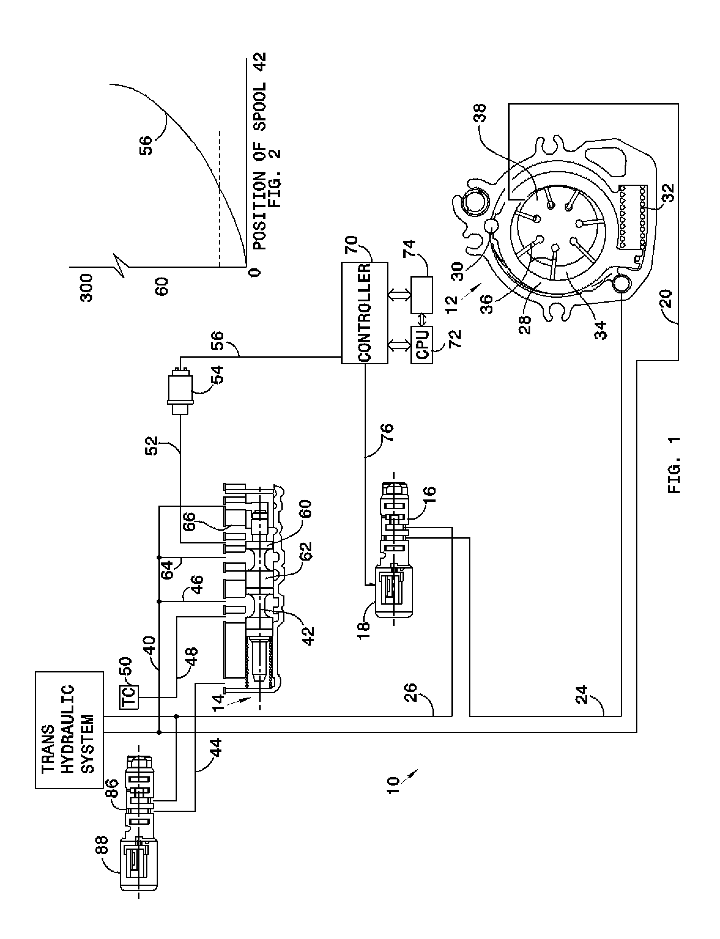
[0018]Referring now to the drawings, there is illustrated in FIG. 1 a hydraulic circuit 10 for an automatic transmission, which includes a variable displacement hydraulic vane pump 12, a main regulator valve 14, and a pump displacement control valve 16, controlled by a variable force solenoid 18.

[0019]Hydraulic fluid exiting pump 12 is carried in line 20 to supply hydraulic fluid for the transmission. Line 24 carries pump displacement control pressure from valve 16 to pump 12. Solenoid feed pressure is carried in line 26 to valve 16 and 86. When pressure in line 24 is high, the pump control ring 28 pivots counterclockwise about point 30 in opposition to the force of a compression spring 32. This pivoting reduces the volume 34 through which the vanes 36 on the pump rotor 38 rotate, i.e., the pump displacement, and the flow rate of fluid exiting the pump 12. When pressure in line 24 is low, the pump control ring 28 pivots clockwise, increasing the pump displacement and the flow rate o...


PUM


Abstract

A system for controlling fluid flow rates in a transmission includes a pump having variable displacement and providing a pressurized fluid source, a regulating valve communicating with the fluid source and a pressure sensor, the pressure sensor producing a variable control signal whose magnitude represents a degree to which fluid flow requirements of the transmission are being provided by the fluid source, and an actuating valve producing a pressure that changes the pump displacement in response to the magnitude of the control pressure.

Description

BACKGROUND OF THE INVENTION[0001]1. Field of the Invention[0002]This invention relates generally to an electro-hydraulic control of an automatic transmission, particularly to a control system having active control of pump displacement.[0003]2. Description of the Prior Art[0004]Most current automatic transmissions use a solenoid in conjunction with a regulator & latch valve to control independently the clutches and brakes, which are applied and released to produce the transmission gear ratios. A valve body assembly that includes a solenoid with a regulator & latch valve for this purpose requires many layers to accommodate all of the solenoids and valves. Such a valve body adds cost and size due to the many valve body layers, and it creates hydraulic response time delays due to the multiple stages from solenoid output to regulator valve input to regulator output, which must be controlled. Further, these delays are temperature sensitive.[0005]Conventional automatic transmissions use bl...

Claims


Application Information

Patent Timeline
Patent Type & Authority Patents(United States)
IPC IPC(8): F04B49/00
CPCF16H61/0021F16H57/0435
Inventor FRAIT, STEVE A.
Owner FORD GLOBAL TECH LLC
Why Eureka
Try Eureka