Battery charger with high frequency transformer

a high-frequency transformer and battery-charger technology, which is applied in the direction of magnets, magnetic bodies, safety/protection circuits, etc., can solve the problems of large diameter wires used in battery-charger power supply transformers that tend to deform or bulge, and the coil may not fit within the winding window of the bobbin, so as to reduce the leakage inductance

Active Publication Date: 2012-05-29
ILLINOIS TOOL WORKS INC
View PDF9 Cites 19 Cited by
  • Summary
  • Abstract
  • Description
  • Claims
  • Application Information

AI Technical Summary

Benefits of technology

[0019]The invention comprises, in yet another form thereof, a method of manufacturing a battery charging system, where the method comprising the steps of: constructing a battery charging power supply including electrical connections for receiving a high-frequency transformer; forming a high-frequency transformer by: providing a first coil; winding a second coil concentric to the first coil; compressing the first coil and the second coil together to reduce the leakage inductance between the first coil and the second coil to a desired value; and mounting the high-frequency transformer to the battery charging power supply through the electrical connections.

Problems solved by technology

Having coil windings with rectangular or square cross sections can be problematic in charging applications however.
This is because the large diameter wires used in battery-charger power supply transformers have a tendency to deform or bulge at locations where the winding direction changes quickly (e.g., at the corners when wound around a bobbin having a square or rectangular cross section).
As a result, the coil may not fit within the winding window of the bobbin in those areas.
Another problem with using large diameter wires in battery-charger power supply transformers is that the wire leads to and from these transformers tend to be less flexible than smaller wire leads.
Another problem with battery-charger, power supply transformers, especially battery-charger, power supply transformers operating at high frequencies, is leakage inductance.
The presence of high leakage inductance in these transformers can cause several problems.
The primary and secondary coils in leaky transformers are more susceptible to overheating.
Finally, the energy stored in the leakage inductance can be detrimental to transistor switching circuits in the battery-charger power supply.
Release of this stored energy can cause ringing, transistor failure and timing issues.

Method used


Image

  • Battery charger with high frequency transformer
  • Battery charger with high frequency transformer
  • Battery charger with high frequency transformer

Examples


Embodiment Construction

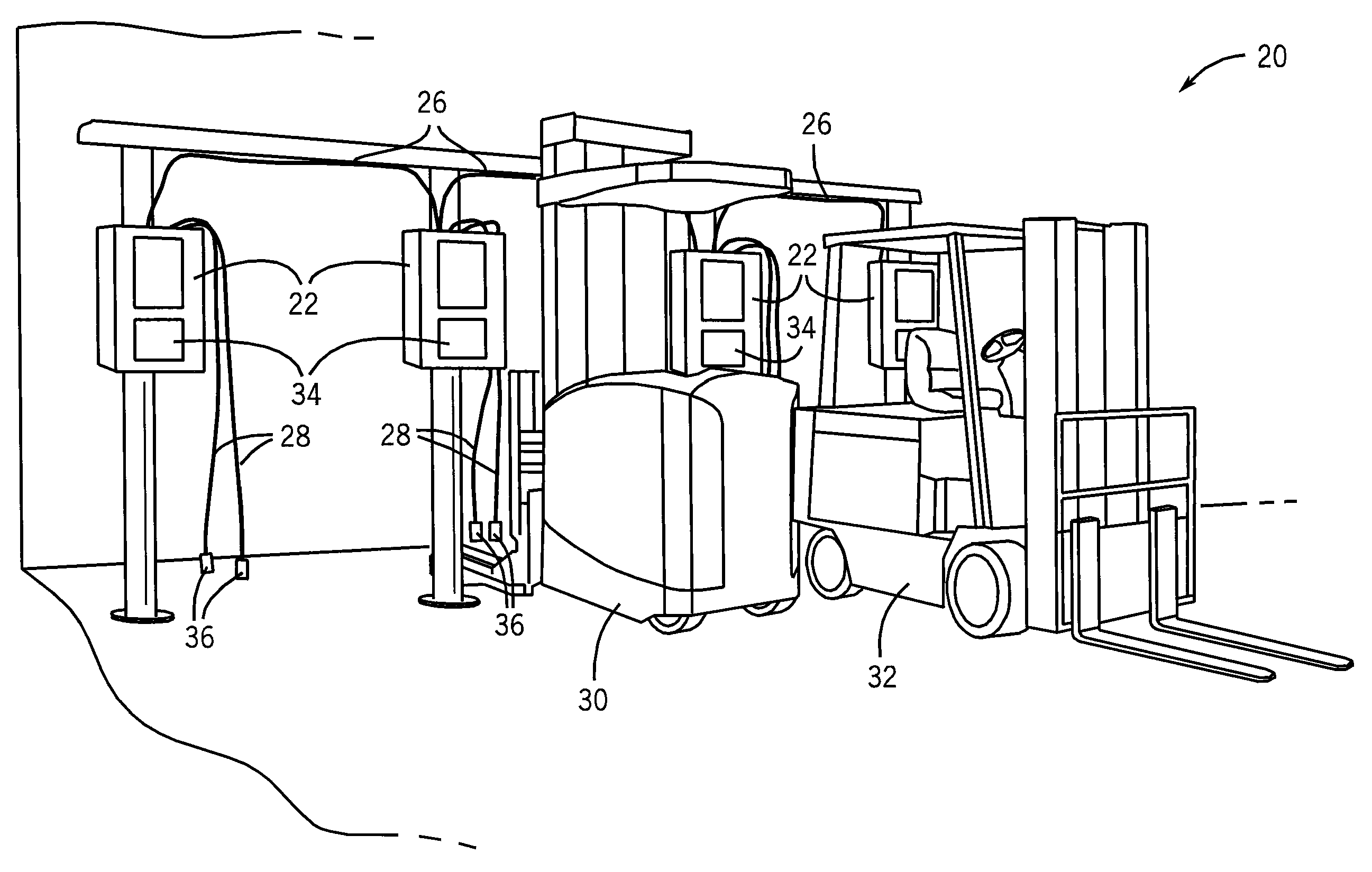
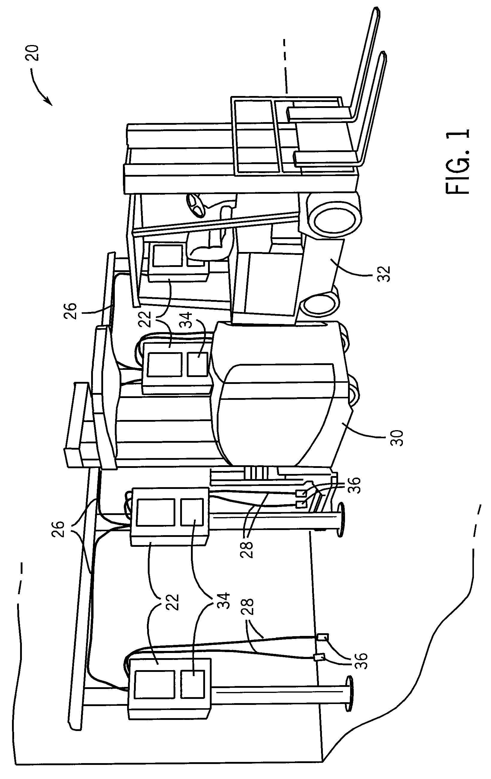
[0036]Referring now to the drawings, and more particularly to FIG. 1, a battery charging system 20 includes a plurality of battery-charging, power supplies 22 are interconnected via a series of cables 26 in daisy-chain configuration to share a common input power. While illustrated in a daisy-chain configuration, it is contemplated that the present invention may be utilized in stand-along, battery-charging, power supplies and non-daisy chained configuration. Extending from each battery-charging power supply 22 is a pair of battery-charging cables 28 designed to carry a battery-charging power (such as a DC current at an appropriate battery system voltage) for charging the battery systems of battery-powered systems, such as a lift truck 30, forklift 32, and / or other battery powered vehicles / systems. Battery charging system 20 can also include a battery module (not shown) which is carried by, and is connected to, the battery systems of vehicles 30, 32 and the like, and provides some con...


PUM

PropertyMeasurementUnit
voltagesaaaaaaaaaa
voltagesaaaaaaaaaa
diameteraaaaaaaaaa

Abstract

A battery-charging system includes a power supply having a high-frequency transformer and is configured to deliver a battery charging power to charge at least one battery. The high-frequency transformer has a bobbin including an elongated top and bottom surfaces and first and second substantially semi-circular end surfaces connecting the top surface with the bottom surface to form an elongated first coil winding surface having a central axis. A first coil is wound around the first coil winding surface, and a second coil is magnetically coupled to the first coil and wound thereto.

Description

REFERENCE TO RELATED APPLICATIONS[0001]Not applicable.STATEMENT REGARDING FEDERALLY SPONSORED RESEARCH OR DEVELOPMENT[0002]Not applicable.FIELD OF THE INVENTION[0003]The present invention relates generally to battery charging systems and, more particularly, to high frequency transformers in industrial-type, fast charging, battery charging systems.BACKGROUND OF THE INVENTION[0004]Fast-charging, battery charging systems are distinguished from other battery charging systems in that they operate to produce a battery charging output with a higher kilowatt output and approximately twice, or greater, the charging rate than traditional battery charging systems. An industrial-type, fast charging, battery charging system can include a power supply connected to one or more charging stations, and the charging stations can have output currents up to 500 A or greater, and power outputs up to 30 kW and greater. Compatible battery voltages are typically 12 to 80 volts from a lead-acid battery or ba...

Claims


Application Information

Patent Timeline
Patent Type & Authority Patents(United States)
IPC IPC(8): H02J7/00
CPCH01F27/325H02J7/00B60L11/1824H02J7/0029H01F27/323H01F30/04H01F2038/026Y10T29/4902Y02T10/7005Y02T90/12Y02T90/121Y02T90/14Y02T10/7072H01F2005/022B60L53/302Y02T10/70
Inventor ALTEKRUSE, KENNETHKIMBALL, JAMES D.SIGL, DENNISVOGEL, BERNARD J.LONIGRO, JEFFREY
Owner ILLINOIS TOOL WORKS INC
Why Eureka
Try Eureka