Methods of optimizing the location of an aircraft on the ground and in the take-off and landing phases

a technology of aircraft and take-off and landing, applied in the field of methods and systems for optimizing the location of aircraft in airports, can solve problems such as trouble for the crew, and achieve the effect of optimizing the calculation

Active Publication Date: 2012-05-29
THALES SA
View PDF27 Cites 2 Cited by
  • Summary
  • Abstract
  • Description
  • Claims
  • Application Information

AI Technical Summary

Benefits of technology

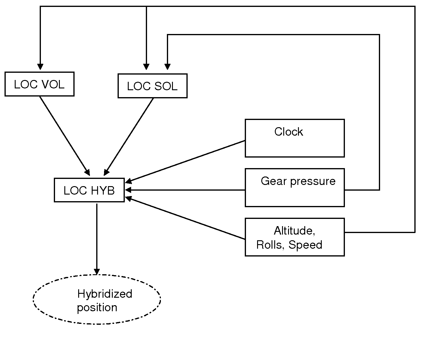
[0023]The invention proposes a method of optimizing the calculation of the position of the aircraft in all the take-off phases, that is, from its stopping point, just before throttle-up, to a point in the flight plan at which the flight is considered stabilized. Moreover, the invention makes it possible to optimize the calculation of its position in the landing phase.
[0024]The invention makes it possible to implement a method, in the air-ground and ground-air transition phases, of hybrid calculation between its position measured on the basis of an in-flight locating system and its position measured on the basis of a ground locating system.

Problems solved by technology

However, there is a problem in the transitional take-off and landing phase during the changeover from one locating system to the other in which the accuracies of the locating systems do not allow for a continuous changeover of the position of the aircraft.
This problem causes trouble for the crew, notably for the display of the aeroplane position when there is a changeover between the display of the airport map and the display of the flight plan.
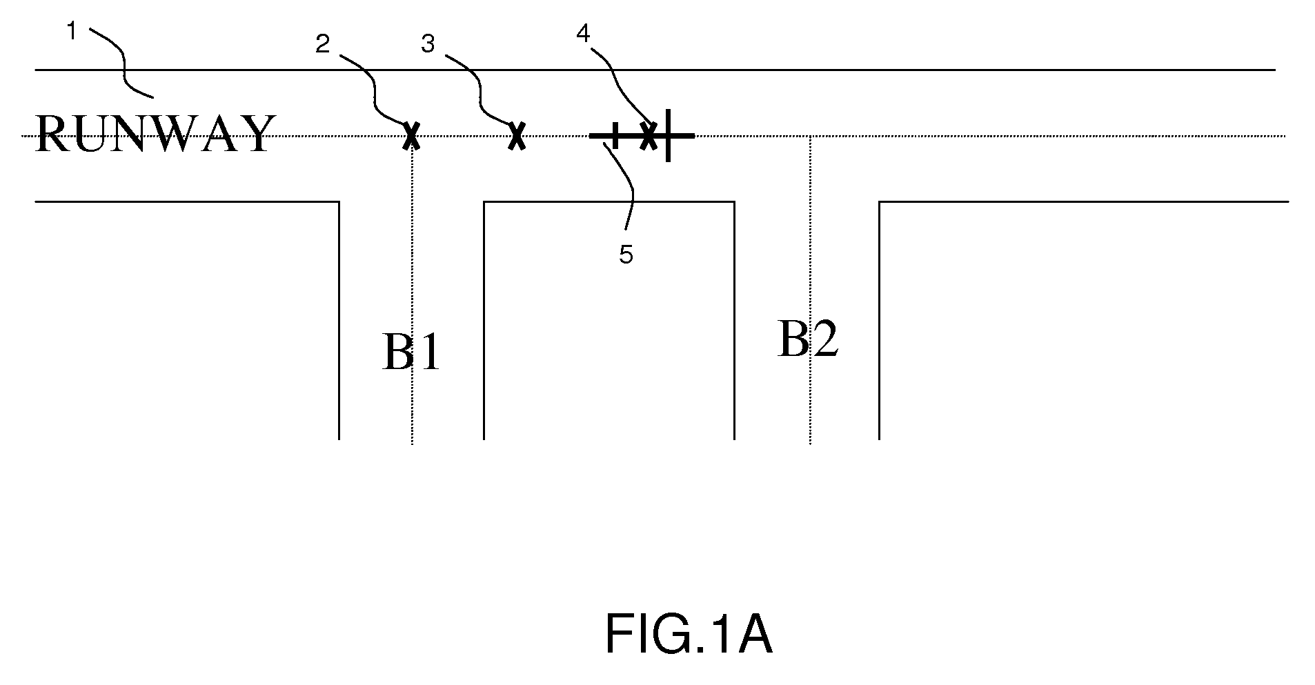
Moreover, in the take-off phase, there is a problem associated with the offset between the theoretical position, called the designated take-off point, and the actual position of the aircraft on the runway just before throttle-up.
This problem is caused either by the uncertainty concerning the position of the aircraft on the runway relative to the theoretical point, or from an access to the runway via an access ramp not originally planned, a change having been made during the rolling phase.

Method used


Image

  • Methods of optimizing the location of an aircraft on the ground and in the take-off and landing phases
  • Methods of optimizing the location of an aircraft on the ground and in the take-off and landing phases
  • Methods of optimizing the location of an aircraft on the ground and in the take-off and landing phases

Examples


Embodiment Construction

[0050]The invention makes it possible to optimize the calculation of the position of the aircraft notably by a first method corresponding to the take-off phase and a second method corresponding to the landing phase, the inventive concepts of the two methods being the same.

[0051]During the take-off phase, a first method according to the invention comprises several steps.

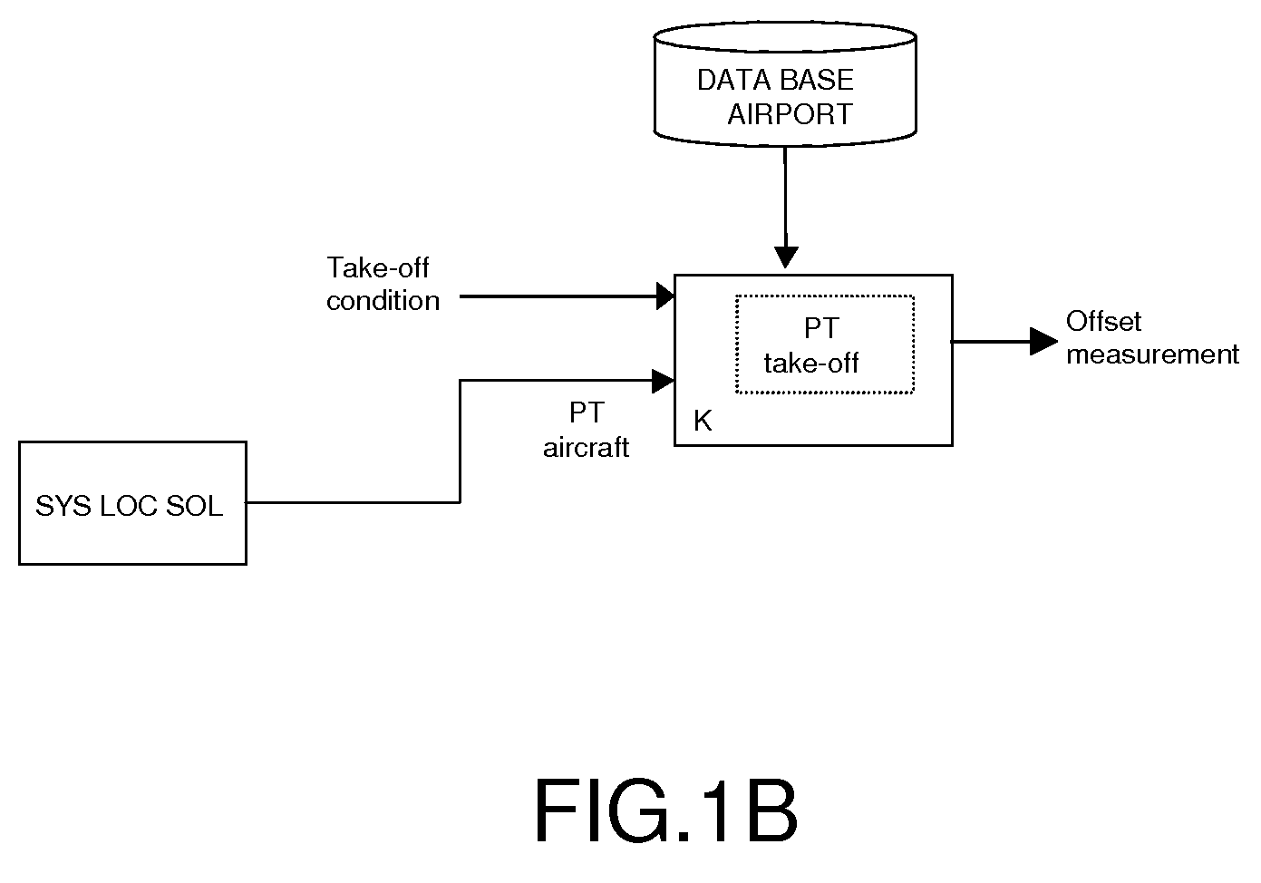
[0052]A first step of the first method consists in automatically readjusting, before throttle-up, the theoretical take-off position in the onboard computer. The theoretical take-off position is generally designated on preparation of the flight by the crew.

[0053]In the preparation of the flight generally performed in the parking area, the pilot initializes, through the onboard computer, the inertial units and the current position of the aircraft. The crew has to select an access ramp to the runway or at least one element of the airport database in order to define the runway entry point.

[0054]The take-off comprises a ro...


PUM


Abstract

The present invention relates to the field of methods and systems for optimizing the locating of an aircraft in airports and, more particularly, in the take-off and landing phases, and notably in the air-ground and ground-air transition phases. The method of optimizing the locating of an aircraft during the take-off or landing phase comprising a transition step (21), the latter being defined between two events (A0, AS), the first event being a condition of contact between the aircraft and the runway and the second event being a threshold condition defining a stabilized flight phase, is wherein the transition step (21) comprises the determination of at least one “transition position” of the aircraft by a weighting between the “ground position” (LOC_SOL) determined by the ground locating system and the “flight position” (LOV_VOL) determined by the in-flight locating system.

Description

RELATED APPLICATIONS[0001]The present application is based on, and claims priority from, French Application Number 0800674, filed Feb. 8, 2008, the disclosure of which is hereby incorporated by reference herein in its entiretly.TECHNICAL FIELD[0002]The present invention relates to the field of methods and systems for optimizing the locating of an aircraft in airports and, more particularly, in the take-off and landing phases, and notably in the air-ground and ground-air transition phases.BACKGROUND OF THE INVENTION[0003]Nowadays, in most aircraft, the calculation of the aeroplane position is performed on the basis of a ground locating system for the airport rolling phases and an in-flight locating system for take-off, landing and cruising flight.[0004]With respect to the ground locating system, generally the latter is handled by a computer, of FMS type, the acronym signifying “Flight Management System”. In particular, the computer fulfils the flight plan display, computation and aer...

Claims


Application Information

Patent Timeline
Patent Type & Authority Patents(United States)
IPC IPC(8): G06G7/70G01S19/21G01S19/26
CPCG01S19/14G01S19/15G01S19/48G08G5/0065G08G5/025G08G5/065
Inventor COULMEAU, FRANCOISMARTY, NICOLASCORDONNIER, ALAIN
Owner THALES SA
Why Eureka
Try Eureka