Control device for electric rotating machine and method of controlling the machine
a technology of control device and electric rotating machine, which is applied in the direction of programme control, dynamo-electric converter control, instruments, etc., can solve the problems of discontinuous change of controlled voltage and difficulty in maintaining a and achieve the effect of high controllability of the machin
- Summary
- Abstract
- Description
- Claims
- Application Information
AI Technical Summary
Benefits of technology
Problems solved by technology
Method used
Image
Examples
first embodiment
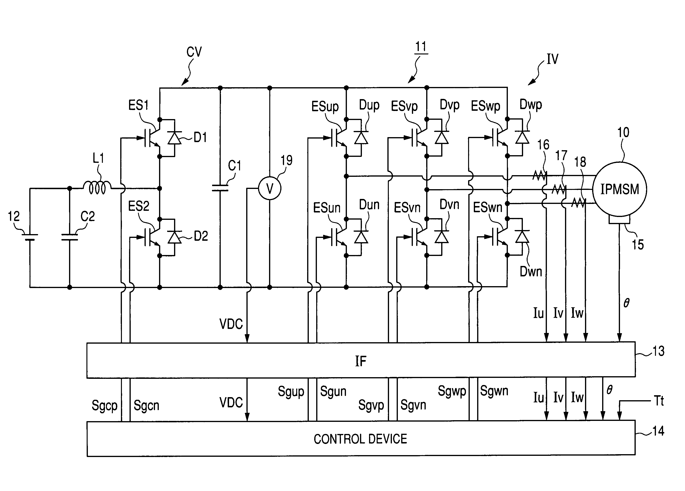
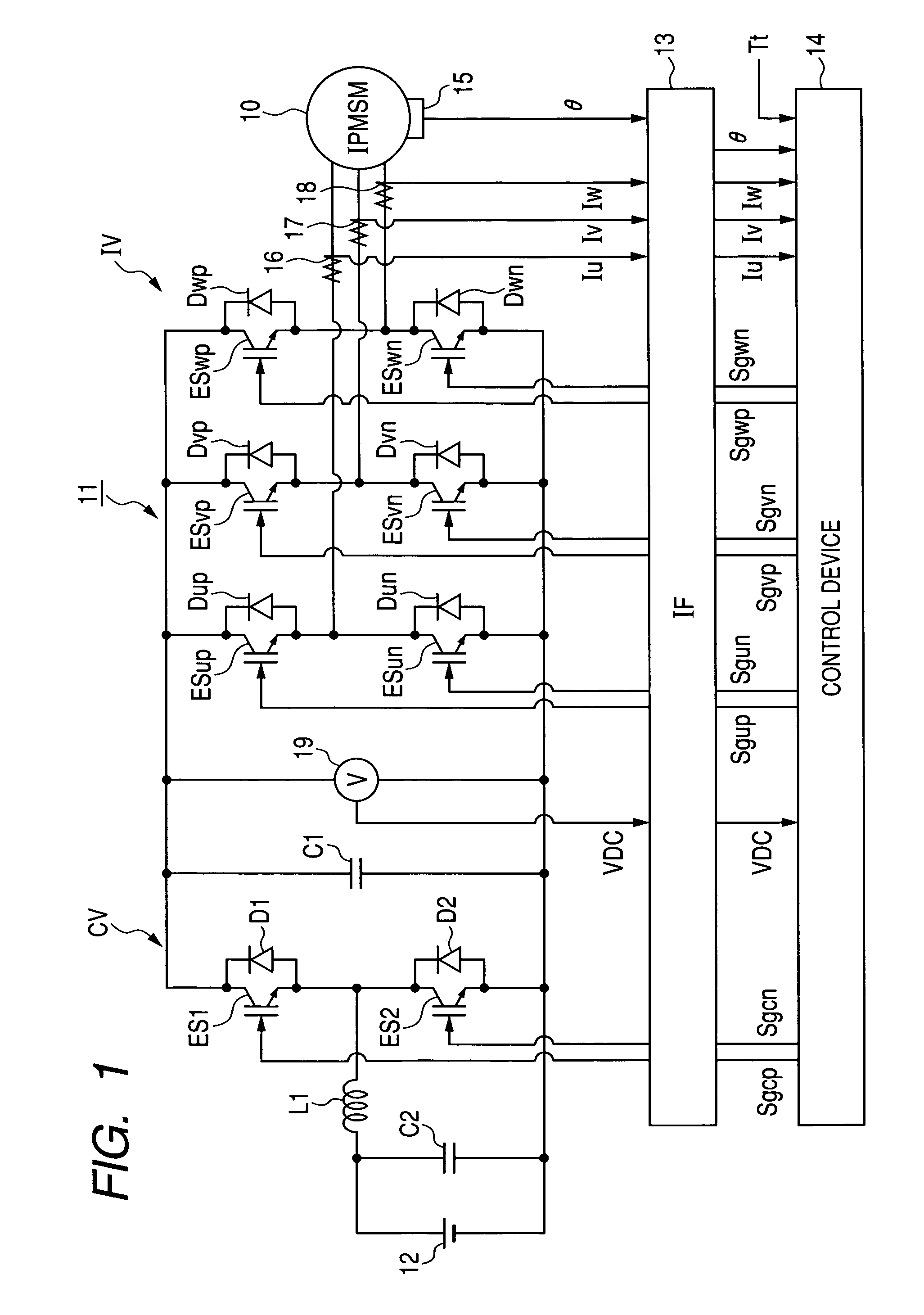
[0058]FIG. 1 is a view showing the structure of a control system for a motor generator according to the first embodiment.
[0059]As shown in FIG. 1, electric power of a high-voltage battery 12 is adjusted in a control system 11 and is supplied to a motor generator 10. This power generating system including the generator 10, the system 11 and the battery 12 is, for example, mounted on a hybrid vehicle. The generator 10 represents an electric rotating machine whose feature is the presence of magnetic saliency. More specifically, the generator 10 is a three-phase interior permanent magnet synchronous motor (IPMSM). This motor has a rotor, permanent magnets having salient poles and being disposed around a shaft of the rotor so as to be protruded from the shaft, a stator surrounding the rotor, and three windings (i.e., a u-phase winding, a v-phase winding and a w-phase winding) wound on the stator.
[0060]The control system 11 has a boost converter CV for boosting the voltage (e.g., 288V) of...
second embodiment
[0190]In the first embodiment, the quantitative value Q1 of the higher harmonic waves is estimated according to the relation (c3). Therefore, the contribution of each higher-order harmonic wave on the quantitative value Q1 is substantially the same as the contribution of any of the other higher-order harmonic waves on the quantitative value Q1.
[0191]However, as the order of the higher harmonic wave becomes low, torque ripple caused in the torque of the generator 10 by the higher harmonic wave of the controlled voltage Vc is increased. To reduce the torque ripple caused by the higher harmonic waves, it is preferable that, as the order of the higher harmonic wave becomes low, the contribution of the higher harmonic wave on the quantitative value Q1 is decreased.
[0192]In the second embodiment, to decrease the contribution of the higher harmonic wave on the quantitative value Q1 as the order of the higher harmonic wave becomes low, the amplitude of each n-th higher order (n=2, 3, 4, . ....
third embodiment
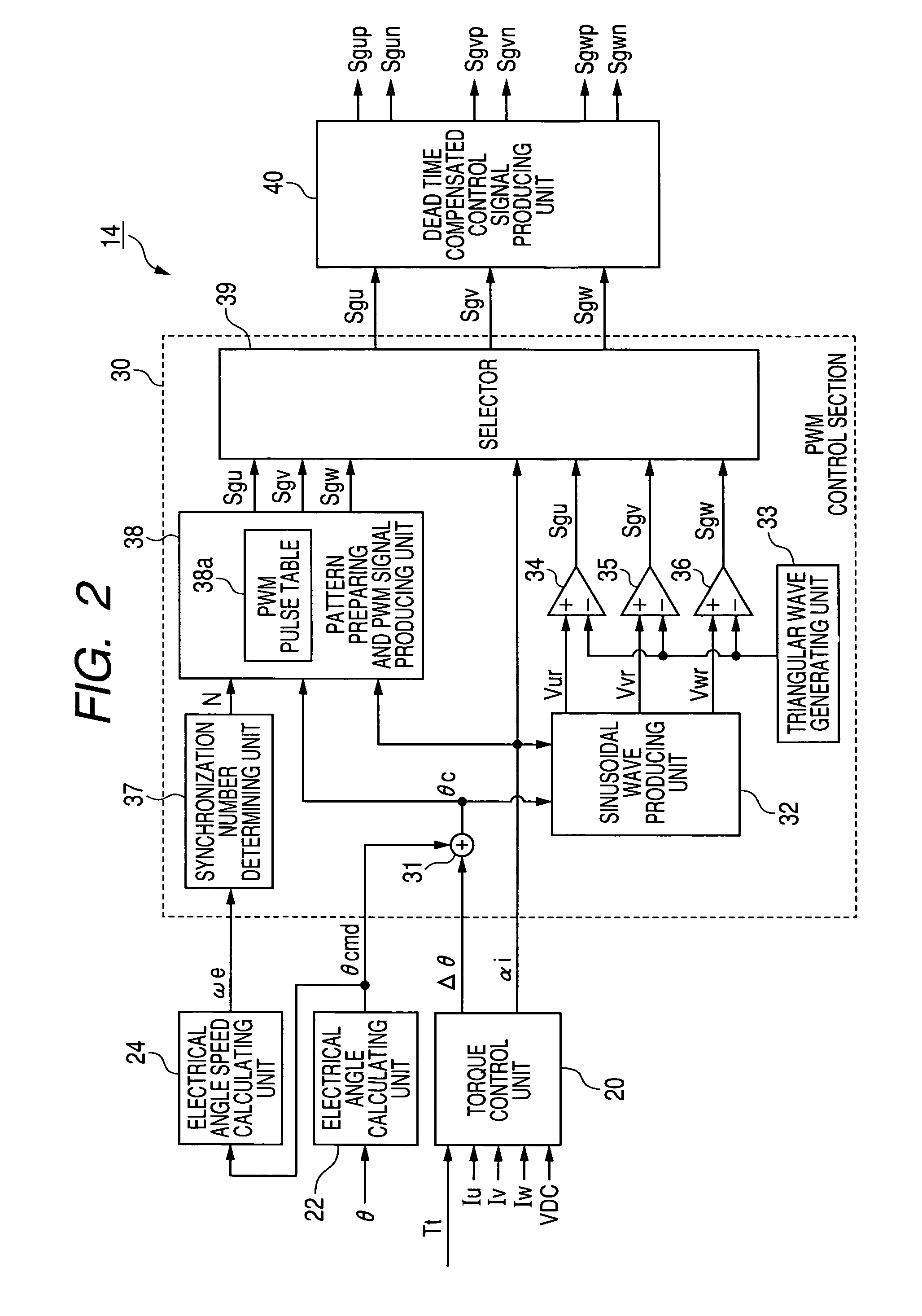
[0202]In the first embodiment, to control the switching elements of the inverter IV and the generator 10 in the pulse pattern control, the production of the PWM signals Sgu, Sgv and Sgw in the control device 14 is performed according to the rotational angle θ detected by the sensor 15. More specifically, the sensor IS renews the angle θ every detecting timing, and the changing timing of the PWM signals is synchronized with the detecting timing of the sensor 15. This synchronization is called angle synchronization based on the angle θ.
[0203]However, when the electrical angular speed we of the generator 10 is low, the phase of the controlled voltage Vc outputted from the inverter IV is controlled at a low controllability. The reason is that the minimum value Δθ(=2πP / C; P denotes the number of pole pairs in the generator 10) detectable by the sensor 15 is fixed due to the resolution C of the sensor 15, regardless of the angular speed as ωe. For example, when the electrical angle cycle ...
PUM
 Abstract
Description
Claims
Application Information
 - R&D
- Intellectual Property
- Life Sciences
- Materials
- Tech Scout
- Unparalleled Data Quality
- Higher Quality Content
- 60% Fewer Hallucinations
Browse by: Latest US Patents, China's latest patents, Technical Efficacy Thesaurus, Application Domain, Technology Topic, Popular Technical Reports.
© 2025 PatSnap. All rights reserved.Legal|Privacy policy|Modern Slavery Act Transparency Statement|Sitemap|About US| Contact US: help@patsnap.com


