
Aircraft having reduced environmental impact

a technology of environmental impact and aircraft, which is applied in the direction of airflow influencers, fuselages, transportation and packaging, etc., can solve the problems of increasing the mass and cost of aircraft, affecting performance, and loss of aircraft, so as to reduce power (and therefore noise and fuel consumption), the effect of not being very noisy and low fuel consumption

Active Publication Date: 2012-06-12
AIRBUS OPERATIONS (SAS)
View PDF10 Cites 11 Cited by
  • Summary
  • Abstract
  • Description
  • Claims
  • Application Information

AI Technical Summary

Benefits of technology

The invention is an aircraft design that reduces environmental impact and noise. It achieves this by positioning the engine and propeller at the rear of the aircraft, away from the horizontal tail plane. The engine is mounted on a cell that extends forward, and the horizontal tail plane is swept forward to form an anti-noise barrier. The cell has a rear boundary that is aligned with the front boundary of the noise zone, maximizing the noise reduction potential. The aircraft may also have two turboshaft engines mounted symmetrically by the wings, with one engine positioned at the rear of the aircraft. Overall, the design reduces noise and fuel consumption while maintaining efficiency.

Problems solved by technology

Thus, with such arrangements, the situation may arise that, if a rotary part of the turbomachine(s) ruptures in an uncontained manner and / or part of the propeller(s) ruptures, debris from these can damage, and even destroy, the horizontal tail plane (and especially the tail box which supports it and which is located at the rear part of the cell) and the vertical tail planes, leading to loss of the aircraft.
Of course, in order to overcome such a disadvantage, it might be possible to conceive of duplicating, strengthening and / or protecting the structure of the said rear part of the cell, but such steps would increase the mass and cost of the aircraft, and at the same time would be detrimental to performance.

Method used


Image

  • Aircraft having reduced environmental impact
  • Aircraft having reduced environmental impact
  • Aircraft having reduced environmental impact

Examples


Embodiment Construction

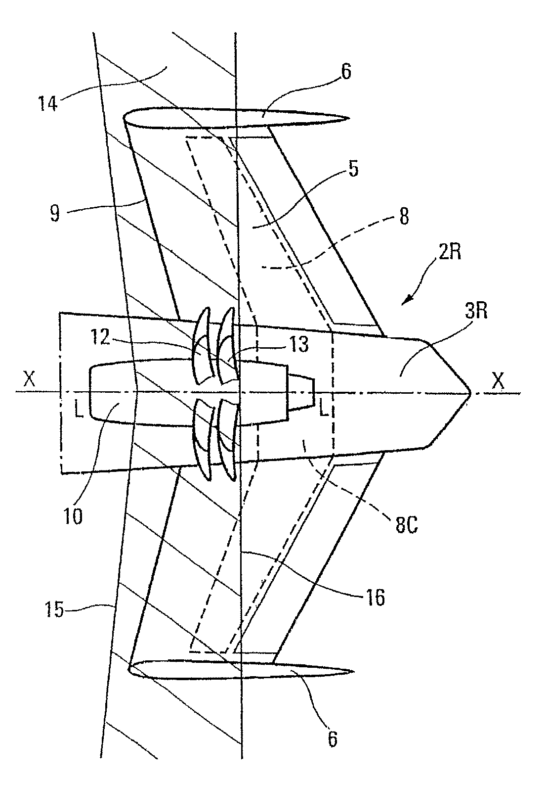
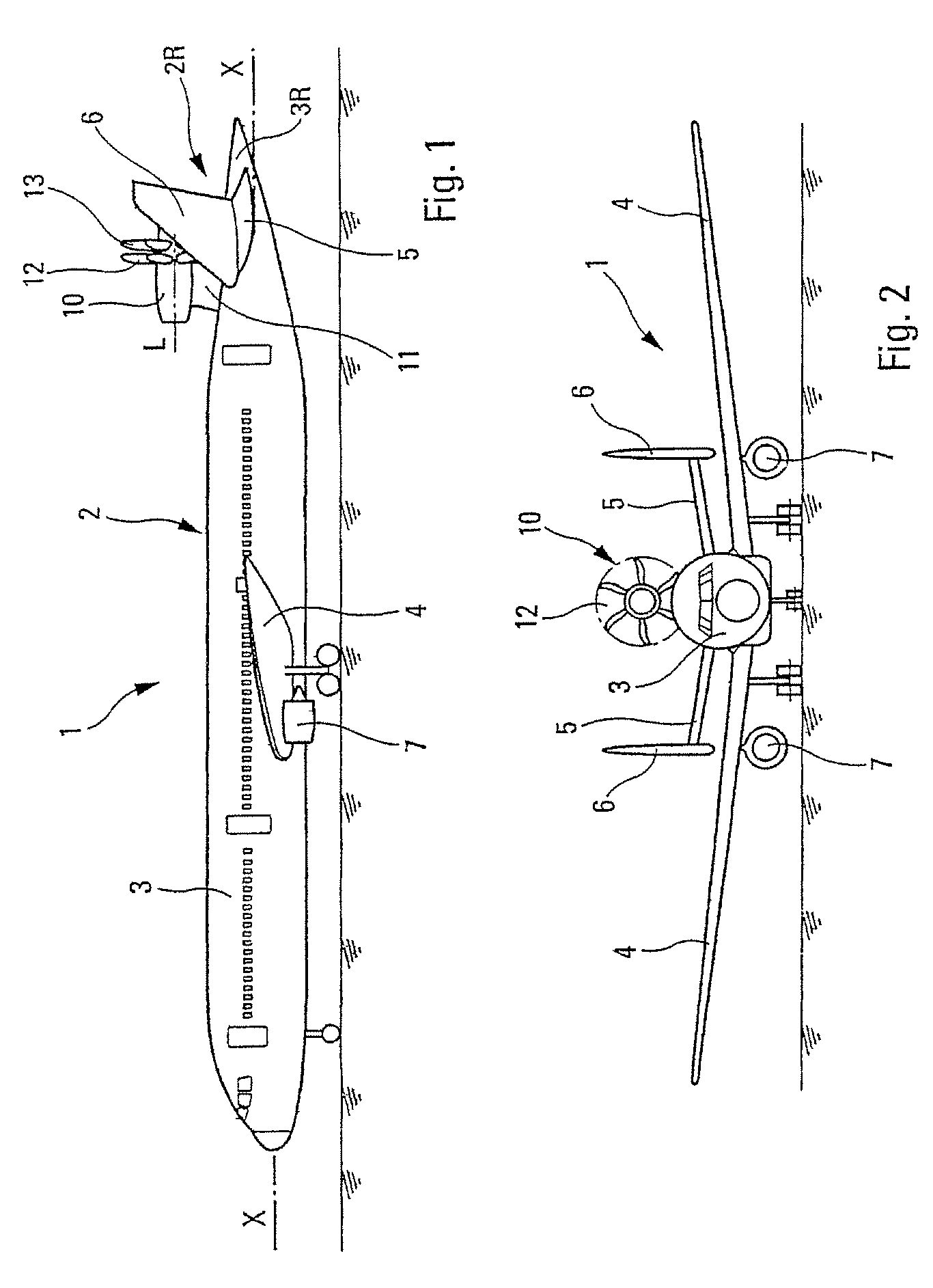
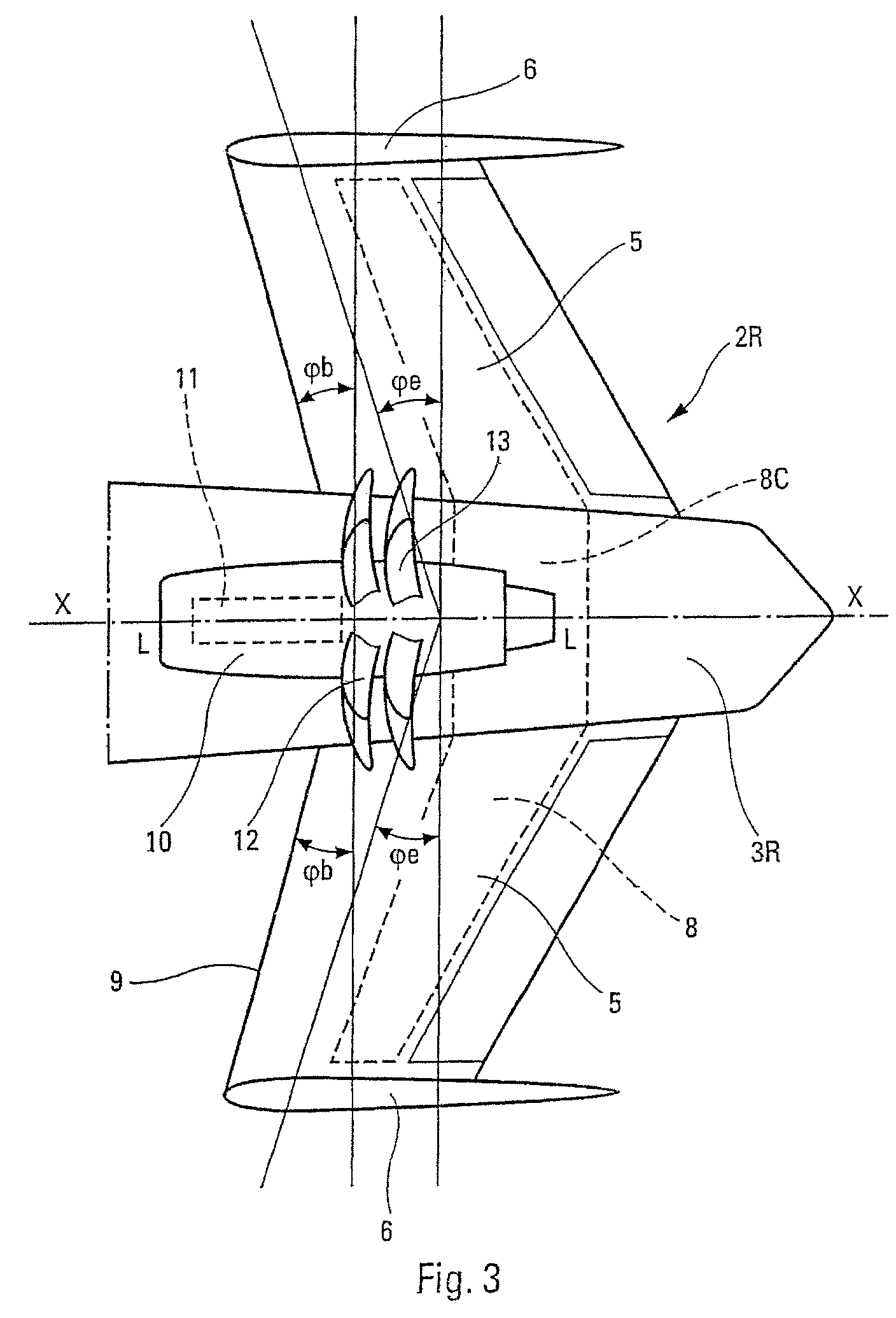
[0027]The commercial airplane 1, according to the invention and depicted schematically in FIGS. 1 to 3 has a longitudinal axis X-X and comprises a cell 2 which consists of a fuselage 3, wings 4, a horizontal tail plane 5 and two vertical tail planes 6. The wings 4 each bear a turboprop engine 7 and the vertical tail planes 6 are positioned at the ends of the horizontal tail plane 5.

[0028]This horizontal tail plane 5 is of the known THS (or PHR) type with variable angle of inclination and is supported by a tail box 8, the central part 8C of which is housed inside the rear part 3R of the fuselage 3. In addition, the horizontal tail plane 5 is swept forward at an angle φe. Likewise, the leading edge 9 of the horizontal tail plane 5 is swept forward at an angle φb.

[0029]At the rear part 2R of the cell 2 (which rear part 2R comprises the rear part 3R of the fuselage 3, the horizontal tail plane 5 and the vertical tail plane 6) is mounted a propeller engine 10 positioned on the back of th...


PUM


Abstract

An aircraft having reduced environmental impact includes at least one engine with at least one propeller carried, at the rear, on the top of the aircraft with the propeller(s) located in vertical alignment with the rear part of a noise barrier cell and the rear face of a burst zone situated forward of the central part of an empennage box.

Description

FIELD OF THE INVENTION[0001]The present invention relates to an aircraft of reduced environmental impact.BACKGROUND OF THE INVENTION[0002]French patent application no. 05 11176, filed on Nov. 3, 2005 in the name of the applicant company describes an aircraft with low fuel consumption which produces little pollution, and which, particularly upon take off and landing, emits only small amounts of noise toward the ground. An aircraft such as this comprises at least one propeller engine, preferably unducted, mounted at the rear of the aircraft, on the back thereof, with its axis at least substantially parallel to the longitudinal axis of the said aircraft. An engine such as this may, for example, be a turboprop with a single propeller or alternatively may be a prop fan with contra-rotating propeller and fan. In addition, the cell of the said aircraft, the rear part of which comprises a horizontal tail plane and two vertical tail planes, these being positioned one at each end of the said ...

Claims


Application Information

Patent Timeline
Patent Type & Authority Patents(United States)
IPC IPC(8): B64C5/02B64D27/00
CPCB64D27/14B64D2027/005Y02T50/66Y02T50/60
Inventor GALL, PIERRE-EMMANUELCROS, CHRISTOPHE
Owner AIRBUS OPERATIONS (SAS)
Learn More