High energy efficiency biomass conversion process

a biomass conversion and high energy efficiency technology, applied in the direction of combustible gas coke oven heating, separation processes, waste based fuel, etc., can solve the problems of tensile smoking and relatively low throughput of single-reactor systems

Active Publication Date: 2012-06-12
SMART TERRA CARE LLC
View PDF48 Cites 26 Cited by
  • Summary
  • Abstract
  • Description
  • Claims
  • Application Information

AI Technical Summary

Benefits of technology

[0015]The preferred torrefaction and carbonization reactors of the invention are substantially identical, save for the materials used in the construction thereof. Thus, these reactors comprise an elongated, axially rotatable shell having a biomass input adjacent one end thereof and a treated biomass output adjacent the other end thereof, with a housing in surrounding relationship to the shell and defining with the shell an indirect heating zone, and including a hot gas inlet operable to receive hot gas for indirectly thermally treating biomass within the shell, and...

Problems solved by technology

However, the torrefied product still contains heavy VOCs and, if used as a fuel, will have a tendency to “smoke.” Carbonization removes most of the remaining VOCs in the torrefied biomass, leaving a residue which is essentially free of smoke-producing compounds and is composed essentially of fixed carbon.
Thi...

Method used


Image

  • High energy efficiency biomass conversion process
  • High energy efficiency biomass conversion process
  • High energy efficiency biomass conversion process

Examples


example 1

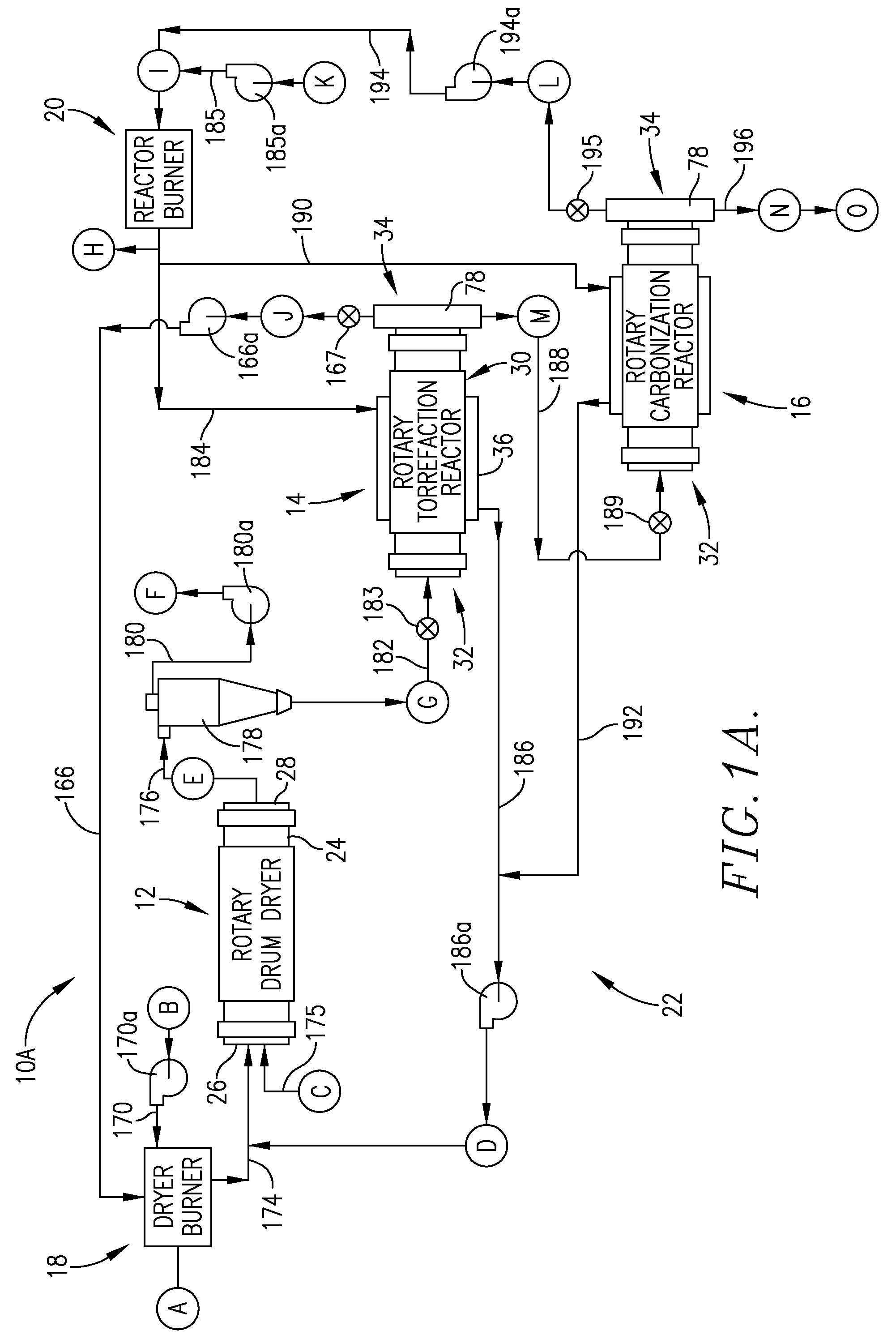
[0045]This is a hypothetical, computer-based example using system 10A for the conversion of a typical wood chip biomass into charcoal product, and production of all of the thermal energy used in the operation of the system, once the process has achieved steady state operation.

[0046]Referring to FIG. 1A, locations A-O are indicated throughout the system 10A. The following legend sets forth the mass-energy balance for the process at these respective locations.[0047]A—dryer burner operation[0048]500 BTU / lb[0049]435 lb / hr VOCs[0050]0.22 MMBtu / hr[0051]B—combustion air to dryer burner[0052]2,327 SCFM[0053]32° F.[0054]40% excess air[0055]C—biomass infeed to dryer[0056]4,300 lb / hr total[0057]2,365 lb / hr solids[0058]1,935 lb / hr water[0059]D—hot gases to dryer[0060]11,164 ACFM[0061]21,647 lb / hr[0062]2.21 MMBtu / hr[0063]770° F.[0064]E—dryer output[0065]2,438 lb / hr total[0066]2,365 lb / hr solids[0067]73 lb / hr water[0068]110° F.[0069]F—vented exhaust gases[0070]8,000 ACFM[007...

example 2

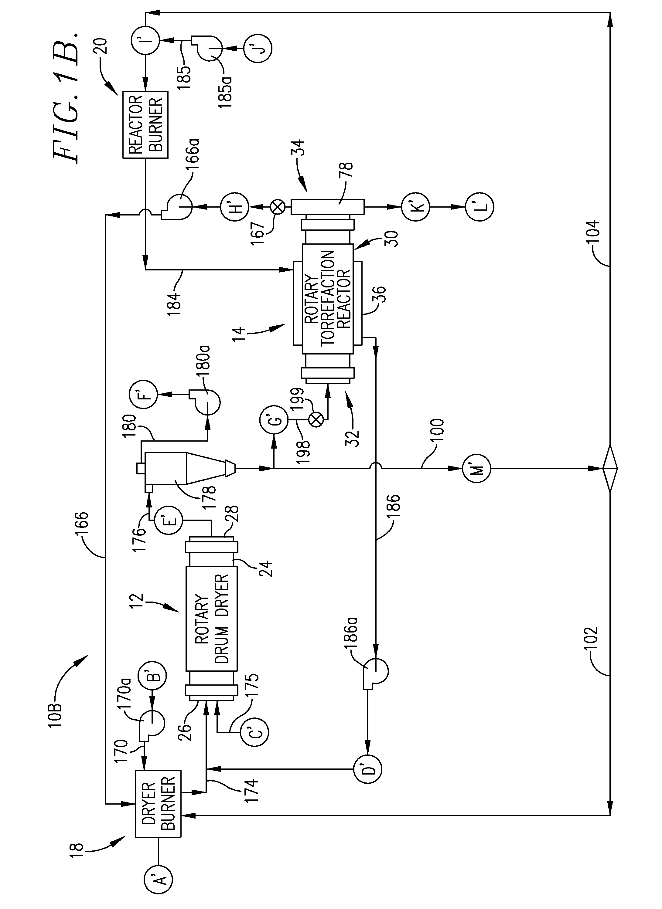
[0112]This is a hypothetical, computer-based example using system 10B for the conversion of a typical wood chip biomass into torrefied product, and production of thermal energy used in the operation of the system, once the process has achieved steady state operation.

[0113]Referring to FIG. 1B, locations A′-M′ are indicated throughout the system 10. The following legend sets forth the mass-energy balance for the process at these respective locations.[0114]A′—dryer burner operation[0115]8,000 BTU / lb dried biomass[0116]362 lb / hr dried biomass[0117]2.90 MMBtu / hr[0118]B′—combustion air to dryer burner[0119]1,223 SCFM[0120]32° F.[0121]175% excess air[0122]C′—biomass infeed to dryer[0123]4,300 lb / hr total[0124]2,365 lb / hr solids[0125]1,935 lb / hr water[0126]D′—hot gases to dryer[0127]2,122 ACFM[0128]5,885 lb / hr[0129]0.50 MMBtu / hr[0130]400° F.[0131]E′—dryer output[0132]2,438 lb / hr total[0133]2,365 lb / hr solids[0134]73 lb / hr water[0135]110° F.[0136]F′—vented exhaust gase...

example 3

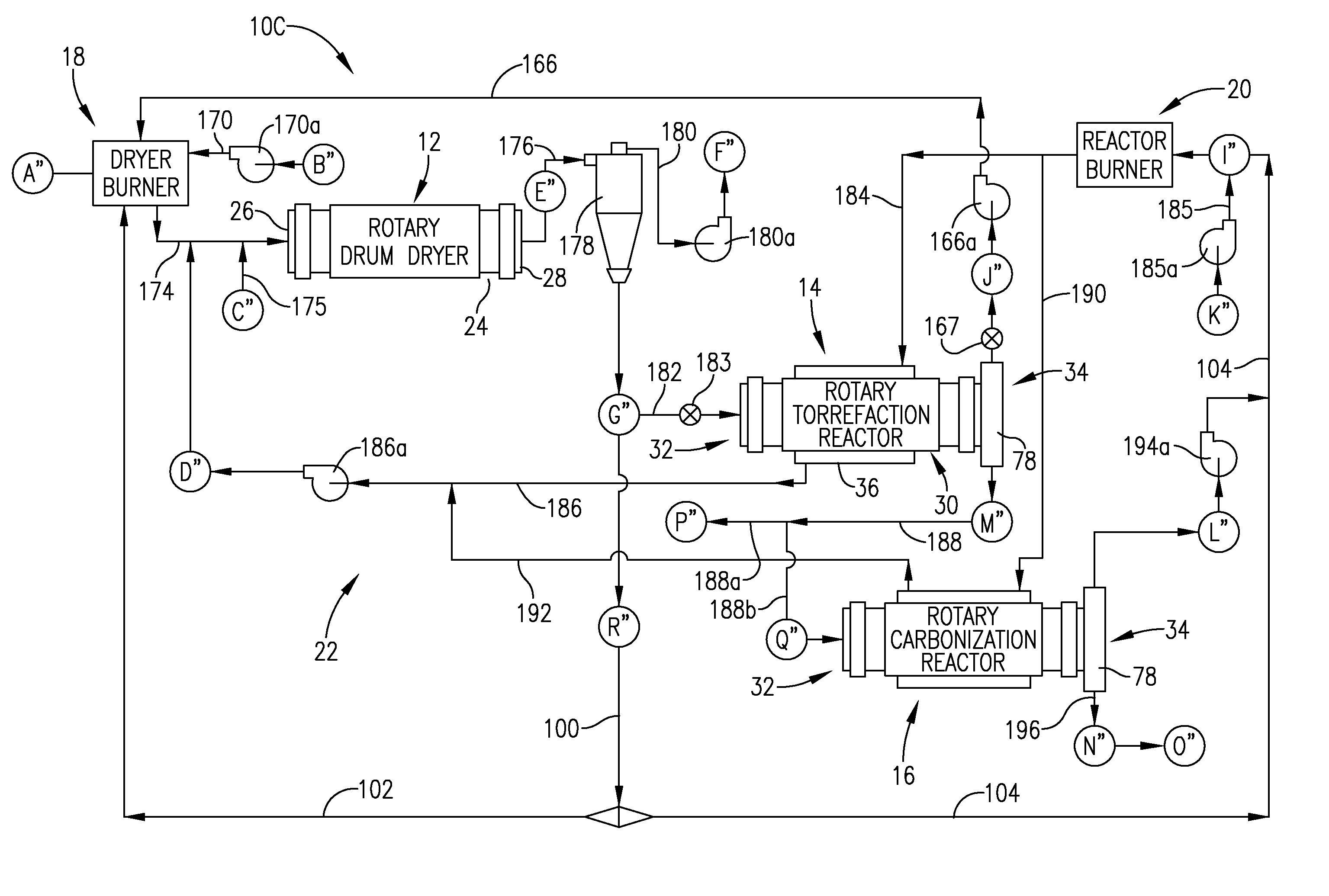
[0169]This is a hypothetical, computer-based example using system 10C for the simultaneous conversion of a typical wood chip biomass into torrefied and charcoal products, and production of a substantial part of the thermal energy used in the operation of the system, once the process has achieved steady state operation.

[0170]Referring to FIG. 1C, locations A″-Q″ are indicated throughout the system 10C. The following legend sets forth the mass-energy balance for the process at these respective locations.[0171]A″—dryer burner—wood / VOC burner[0172]8,000 BTU / lb wood[0173]232 lb / hr wood[0174]1.86 MMBTU / hr[0175]B″—combustion air[0176]713 SCFM[0177]32° F.[0178]150% excess air[0179]C″—biomass infeed to dryer[0180]4,300 lb / hr total[0181]2,365 lb / hr solids[0182]1,935 lb / hr water[0183]D″—hot gases to dryer[0184]4,371 ACFM[0185]8,476 lb / hr[0186]1.36 MMBTU / hr[0187]770° F.[0188]E″—dryer output[0189]2,438 lb / hr total[0190]2,365 lb / hr solids[0191]73 lb / hr water[0192]3% moistu...


PUM


Abstract

Improved, fuel-efficient systems are provided for the processing of biomass, such as wood or crop residues, food waste or animal waste in order to selectively obtain thermally processed final products, such as a combination of torrefied and carbonized final products. The processes involve thermally drying incoming biomass using a dryer employing the hot gas output of a fuel-operated burner. Next, the dried product is torrefied in an indirect torrefaction reactor so as to evolve light volatile organic compounds which are used as a gaseous fuel source for the burner. Some or all of the torrefied product can be recovered, or some or all of the torrefied product is then directed to a separate carbonization reactor coupled with a reactor burner. Carbonization serves to remove most of the remaining VOCs which are used as a gaseous fuel input to the dryer.

Description

CROSS-REFERENCE TO RELATED APPLICATION[0001]This application is a continuation-in-part of application Ser. No. 13 / 347,822, filed Jan. 11, 2012, which is incorporated by reference herein in its entirety.BACKGROUND OF THE INVENTION[0002]1. Field of the Invention[0003]The present invention is broadly concerned with methods and apparatus used in the processing of biomass to yield torrefied and / or carbonized (i.e., charcoal) biomass. More particularly, the invention is concerned with such methods and apparatus whereby starting biomass is initially dried and then torrefied in a specialized indirect torrefaction reactor, with the combustible gases evolved from the biomass during torrefaction being used as a source of fuel for the initial biomass drying step. Preferably, at least a portion or all of the torrefied product may be subsequently carbonized in a separate indirect carbonization reactor, with the combustible gases evolved from carbonization also being used as a source of fuel. The ...

Claims


Application Information

Patent Timeline
IPC IPC(8): C07C1/00C10L5/00C10B1/00
CPCC10B47/30C10B53/02C10B57/02C10L9/08C10L9/083Y02E50/14Y02E50/15Y02E50/30Y02E50/10
Inventor LIVINGSTON, ANDREW D.THOMAS, BIJOY J.
Owner SMART TERRA CARE LLC
Why Eureka
Try Eureka