Position indicator

Active Publication Date: 2012-06-12
WACOM CO LTD
View PDF40 Cites 66 Cited by
  • Summary
  • Abstract
  • Description
  • Claims
  • Application Information

AI Technical Summary

Benefits of technology

[0021]Thus, in the position detecting sensor, the change in the received signal of the AC signal at the position indicated by the position indicator according to the present invention is increased, so that sensitivity of detection of the position indicator in the position detecting sensor is improved.
[0022]According to the present invention, it is possible to provide a position indicator that has a s

Problems solved by technology

Cost is correspondingly increased, and the position indicator compatible with the respective position detecting sensor need to be provided, so that the versatility of the position indicator is impaired.
Thus, signal continuity or phase relation between the received AC signal and the output AC signal may not necessarily be guaranteed.
Thus, because the posi

Method used


Image

  • Position indicator
  • Position indicator
  • Position indicator

Examples


first embodiment

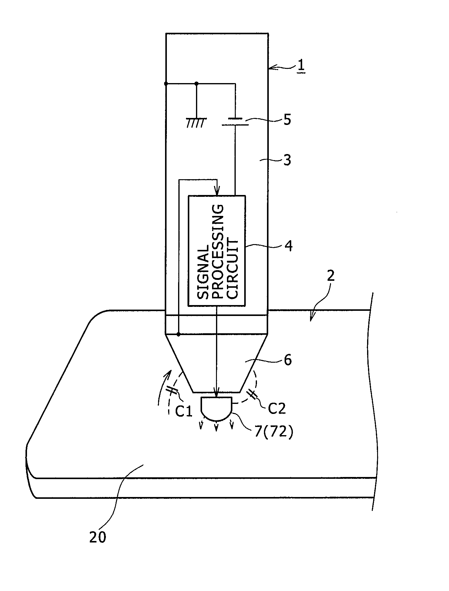
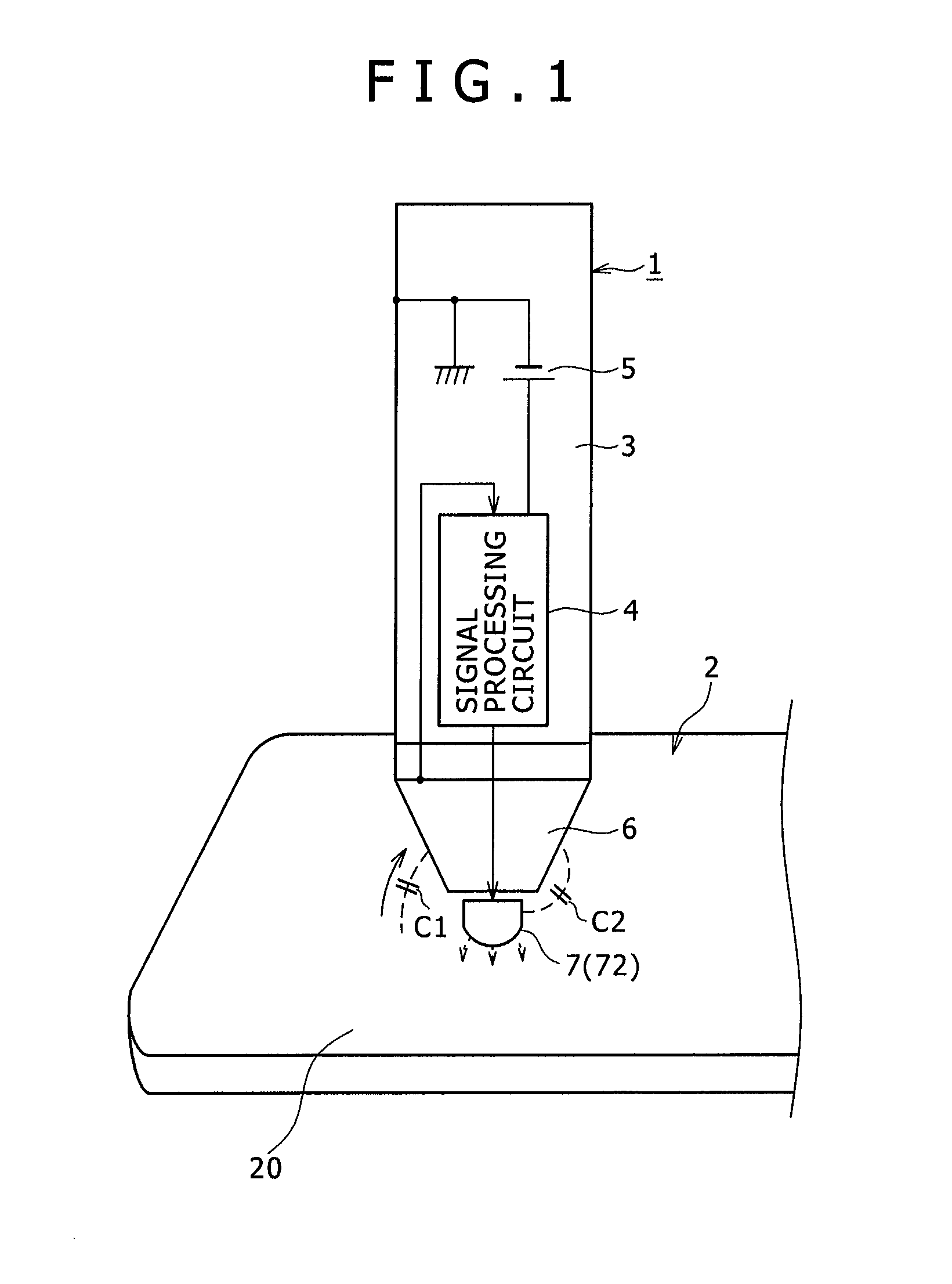
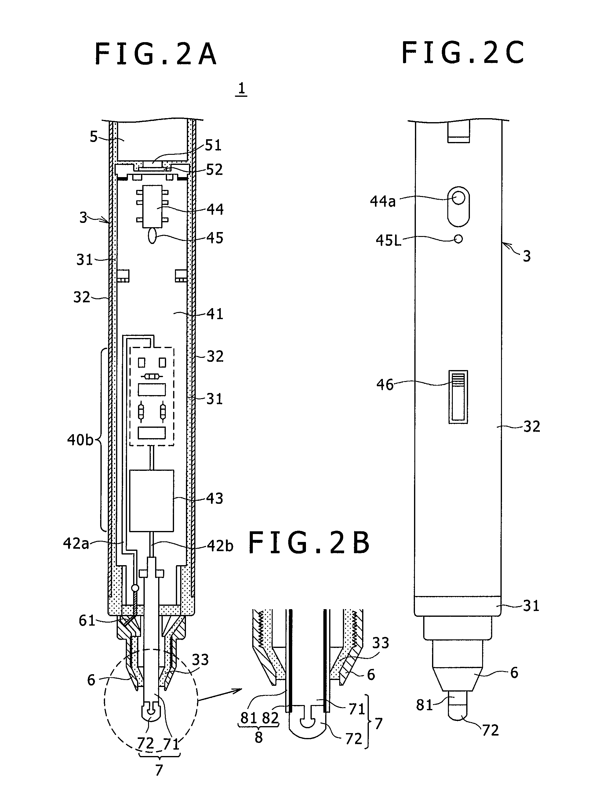
[0034]Preferred embodiments of a position indicator according to the present invention will hereinafter be described with reference to the drawings. FIG. 1 is a diagram of assistance in generally explaining a conceptual structure of a position indicator 1 according to a first embodiment of the present invention and a processing operation of the position indicator 1. FIG. 1 shows a state in which the position indicator 1 is positioned on a plate surface of a capacitance type position detecting sensor 2. FIGS. 2A to 2C are diagrams of assistance in explaining an example of a detailed configuration of the position indicator 1. FIG. 2A is a partial longitudinal sectional view of the position indicator 1 and FIG. 2B is a partial enlarged view of FIG. 2A. FIG. 2C is a diagram showing a part of an external appearance of the position indicator 1. In the present embodiment, the position indicator 1 is formed as a position indicator whose external appearance has the form of a stick-shaped sty...

second embodiment

[0085]In the position indicator 1 according to the first embodiment described above, the first electrode is the peripheral electrode 6, and the second electrode is the central electrode 7. However, it has been found that this configuration causes the following problems depending on the configuration of the position detecting sensor 2.

[0086]In the position detecting sensor 2 used in the first embodiment, the transmitting conductors 23Y and the receiving conductors 24X are both linear conductors. On the other hand, a sensor section 20A of a position detecting sensor 2A in the example of FIG. 5 includes transmitting conductors 230Y1, 230Y2, 230Y64 that do not have a linear shape but have a wide width. Other configurations are similar to those of the first embodiment. Specifically, receiving conductors of the sensor section 20A are linear receiving conductors 24X1, 24X2, 24X64 as in the first embodiment. In the sensor section 20A in the present example, the plurality of transmitting con...

third embodiment

[0099]In the above first and second embodiments, the signal processing sections 40b and 40bA of the signal processing circuits 4 and 4A form a signal enhancing processing circuit with the variable signal amplification factor circuit 420 provided in a stage subsequent to the sense amplifier 410. However, the signal enhancing processing circuit can be of other configurations.

[0100]A third embodiment is a first example of the signal enhancing processing circuit, which enhances an output voltage without using the variable signal amplification factor circuit 420. FIG. 7 is a circuit diagram showing an example of configuration of a signal processing section 40bB of a signal processing circuit 4B in the case of a position indicator according to the third embodiment.

[0101]As shown in FIG. 7, the signal processing section 40bB includes a sense amplifier 410 and an enhancing circuit 430. The enhancing circuit 430 includes a transformer 43 and an inverting amplifier circuit 431. The output of ...


PUM


Abstract

A position indicator is provided for use with a position detecting sensor that carries out position detection by detecting a change in capacitance. The position indicator includes: a first electrode configured to receive an alternating-current (AC) signal from the position detecting sensor; a signal enhancing processing circuit configured to subject the AC signal received via the first electrode to determined signal enhancing processing; and a second electrode different from the first electrode and configured to be supplied with a signal output from the signal enhancing processing circuit. An enhanced signal having a determined correlation with the AC signal received via the first electrode from the position detecting sensor is formed while the enhanced signal is sent out to the position detecting sensor via the second electrode.

Description

CROSS-REFERENCE TO RELATED APPLICATION[0001]The present application claims priority under 35 U.S.C. §119(a) of Japanese Application No. 2010-278002, filed Dec. 14, 2010, the entire content of which is incorporated herein by reference.TECHNICAL FIELD[0002]The present invention relates to a position indicator used in conjunction with a position detecting sensor in which position detection is carried out by detecting a change in capacitance.BACKGROUND ART[0003]In general, a capacitance type position detecting sensor in which position detection is carried out by detecting a change in capacitance needs a certain level of capacitance or higher (normally about 1 pF) that occurs between the position detecting sensor and a position indicator in order to detect the position of the position indicator with high accuracy. Thus, an input operation on the position detecting sensor is performed by a fingertip or a dedicated electrostatic pen having a relatively large area at a time of contact. That...

Claims


Application Information

Patent Timeline
IPC IPC(8): G06F3/033
CPCG06F3/03545G06F3/046G06F3/044G06F3/0441G06F3/0446G06F3/0442G06F3/04162
Inventor ODA, YASUOYAGI, MASAKI
Owner WACOM CO LTD
Why Eureka
Try Eureka