Adaptive optics line scanning ophthalmoscope

a scanning ophthalmoscope and optic line technology, applied in the field of retinal or ocular imaging, can solve the problems of high cost of deformable mirrors and system complexity, and achieve the effect of advancing vision understanding

Active Publication Date: 2012-06-19
PHYSICAL SCI
View PDF84 Cites 57 Cited by
  • Summary
  • Abstract
  • Description
  • Claims
  • Application Information

AI Technical Summary

Benefits of technology

[0009]The invention, in one embodiment, features adaptive optics (AO) integrated into a line scanning opthalmoscope (LSO). The invention fills the niche between SLO instruments that provide wide field but limited resolution for routinely clinical use and the complex, high resolution, high-performance AO instruments. A compact, simplified AO instrument like the AO-LSO, which can be used by ophthalmologists, optometrists, and vision scientists, can advance the understanding of vision and the development of new techniques to detect and treat retinal diseases.
[0010]An AO-LSO can provide lateral resolution sufficient to visualize the cells and structures critical for vision. An AO-LSO has simplied optics, high-speed scanning components, and smaller footprint compared to a traditional research AOSLO. An AO-LSO can be used to visualize, for example, photoreceptors, fine capillaries, nerve fiber bundles, and drusen, new vessel growth, and lesions in a diseased eye. This advance in compact and lower-cost instrumentation can allow for more rapid transition of high resolution AO capabilities to routine clinical use to provide efficient and rapid image acquisition, early disease screening and detection, and enhanced diagnostic yield, and can guide existing and new treatment strategies. The capability to map and visualize retinal structures in unprecedented detail can improve the understanding of disease processes and improved treatment modalities.
[0011]A bench-top AO-LSO instrument can produce high resolution retinal images with only one moving part, a smaller instrument footprint, and fewer of optical components. The AO-LSO can have a moderate field of view (e.g., about 5.5 deg), which allows montages of the macula or other targets to be obtained quickly and efficiently. For example, the entire macular can be rapidly mapped with a 3×3 image montage. Photoreceptors can be resolved and counted within about 0.5 mm of the fovea. The capillaries surrounding the foveal avascular zone can be resolved, as well as cells flowing within them. Individual nerve fiber bundles can be resolved, especially near the optic nerve head, as well as other structures such as the lamina cribrosa. In addition to instrument design, fabrication, and testing, software algorithms can be used for automated image registration, cone counting, and montage stitching.
[0012]Adaptive optics components and a confocal line-scanning (also called line-field) retinal imaging approach (e.g., an AO-LSO system) can provide a reduction in hardware complexity by elimination of a high-speed scanner and associated mirror or lens relays. Lateral resolution and depth sectioning of the confocal line scanning approach can be improved with adaptive optics. For example, about 6-μm diameter photoreceptors can be resolved at eccentricities of about 0.6 μm (e.g., about 2 deg.). About 15-20 μm diameter nerve fiber bundles can be resolved in the nerve fiber layer. The system can resolve fine capillaries surrounding the foveal avascular zone and can visualize the vacuoles in the lamina cribrosa in the optic nerve head. In some embodiments, retinal images can be stitched to map the photoreceptor mosaic across the entire macula (e.g., about 15 deg.). Acquisition software can be used to control and synchronize instrument hardware, including the deformable minor, Hartmann-Shack wavefront sensor (HS-WS), galvanometer, and linear detector. In some embodiments, analysis software is used for automated registration and averaging, cone counting, and generation of montages. In some embodiments, the system includes a high-stroke deformable mirror, only one moving part, half the optical elements (e.g., spherical minors) of a traditional AOSLO setup, and can feature further reduction in hardware.
[0013]The AO-LSO system can include the use of wavefront sensorless AO control algorithms adapted to the line scanning retinal imager. Wavefront sensorless algorithms can extract information on ocular aberrations from the image information itself, rather than from a separate wavefront sensor. The algorithm can process image information efficiently enough to operate in real time (e.g., at about 10 Hz), and can obviate the need for a separate wavefront sensor, resulting in further reduction in system complexity. With implementation of a wavefront sensorless algorithm, the AO-LSO system can include (e.g., can be reduced to) a deformable mirror, a linear detector, a galvanometer, and a spherical mirrors. The implementation of a wavefront sensorless algorithm, therefore, not only decreases the cost to produce a device, but also enables a less complex, easier to operate instrument.

Problems solved by technology

There are currently two barriers to widespread use of AO by clinicians and research scientists.
The first barrier is the high cost of deformable mirrors.
The second barrier is system complexity.

Method used


Image

  • Adaptive optics line scanning ophthalmoscope
  • Adaptive optics line scanning ophthalmoscope
  • Adaptive optics line scanning ophthalmoscope

Examples


Embodiment Construction

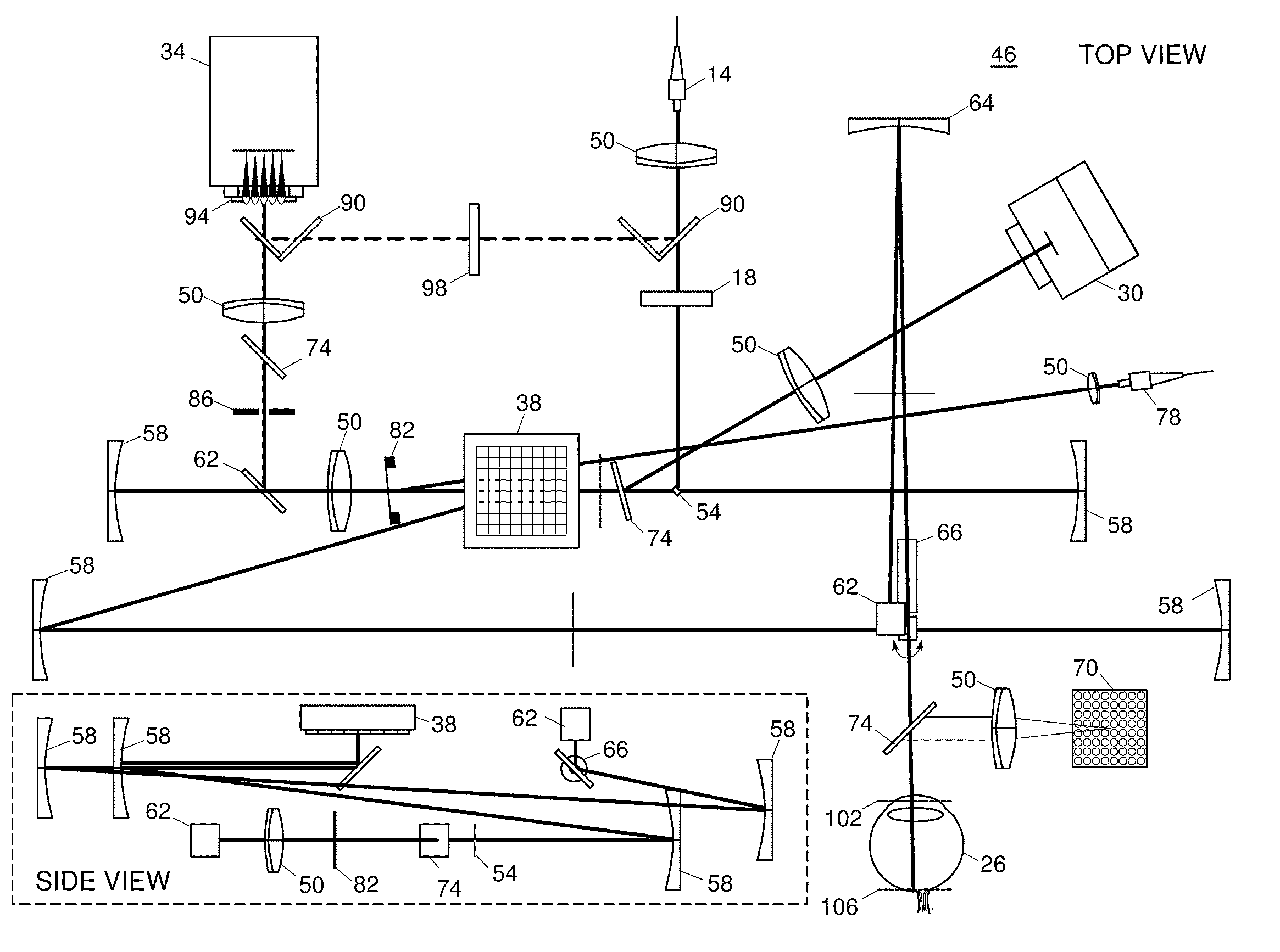
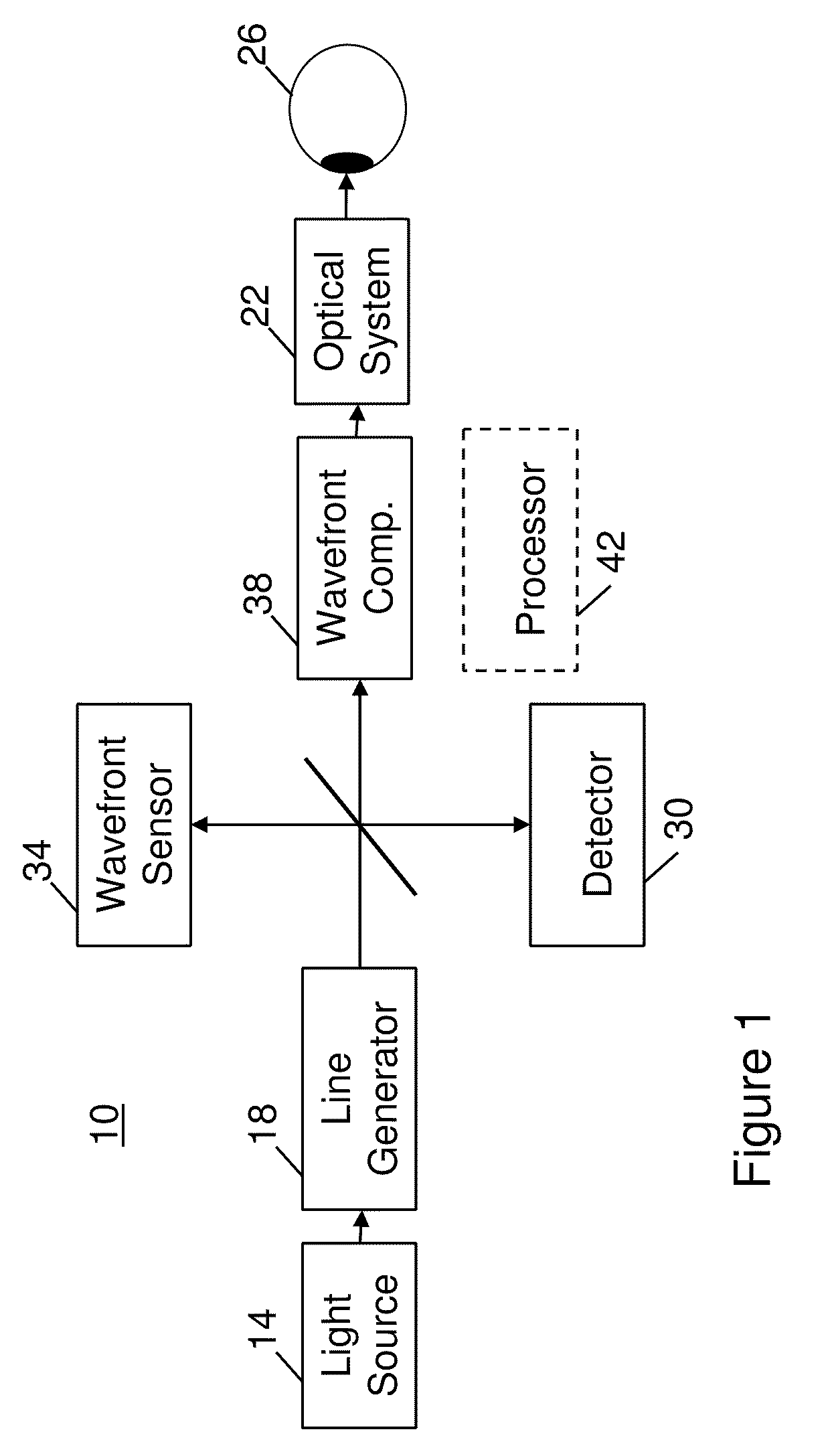
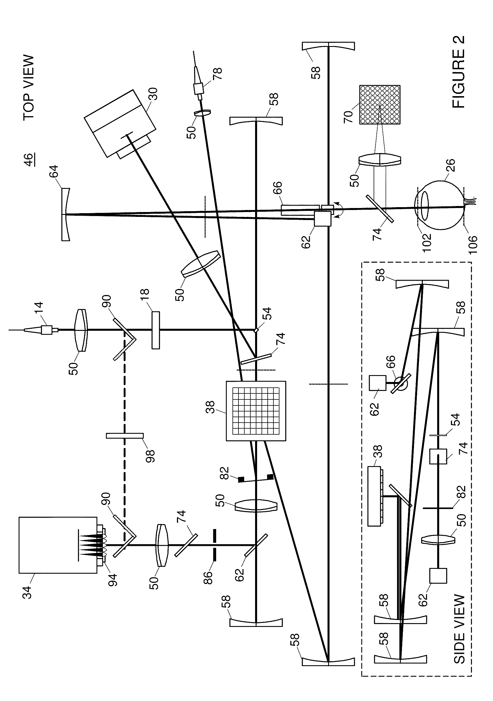
[0048]FIG. 1 shows an optical apparatus 10 including a source 14 of optical radiation and a line generator 18 (e.g., a cylindrical lens) configured to receive the optical radiation and to form the optical radiation into a line of light. An optical system 22 (e.g., a first optical module) includes a scanner and at least one focusing element (e.g., one or more mirrors, one or more spherical minors, one or more parabolic mirrors, one or more lens, or any combination of the aforementioned). The scanner is configured to scan a portion of an eye 26 with the line of light and to descan reflected light from the portion of the eye. The scanner and the at least one focusing element are configured to confocally provide output light in a line focus configuration. A linear array detector 30 is configured to detect the output light in the line focus configuration and to image the portion of the eye. A wavefront sensor 34 is adapted to detect an optical distortion, and a wavefront compensator 38 i...


PUM


Abstract

A first optical module scans a portion of an eye with a line of light, descans reflected light from the scanned portion of the eye and confocally provides output light in a line focus configuration. A detection device detects the output light and images the portion of the eye. A second optical module detects an optical distortion and corrects the optical distortion in the line of light scanned on the portion of the eye.

Description

CROSS-REFERENCE TO RELATED APPLICATION[0001]This application claims the benefit of and priority to U.S. provisional patent application No. 61 / 144,951 filed Jan. 15, 2009, which is owned by the assignee of the instant application and the disclosure of which is incorporated herein by reference in its entirety.GOVERNMENT SUPPORT[0002]The invention was made with government support under NIH National Eye Institute grant R43 EY018509. The government may have certain rights in the invention.FIELD OF THE INVENTION[0003]The invention relates generally to a method and apparatus for retinal or ocular imaging, and more particularly to a method and apparatus for correcting distortions in an optical image of an object (e.g., an eye).BACKGROUND[0004]A confocal imaging system (e.g., scanning laser opthalmoscope, confocal microscope, etc.) rejects light scattered from adjacent or out-of-plane voxels by use of a pinhole in front of the detector conjugate to the focal plane. This can improve image con...

Claims


Application Information

Patent Timeline
Patent Type & Authority Patents(United States)
IPC IPC(8): A61B3/14A61B3/10A61B3/00
CPCA61B3/1025
Inventor HAMMER, DANIEL X.FERGUSON, R. DANIELMUJAT, MIRCEAIFTIMIA, NICUSOR V.
Owner PHYSICAL SCI
Why Eureka
Try Eureka