DC-DC converter
a converter and converter technology, applied in the direction of electric variable regulation, process and machine control, instruments, etc., can solve the problems of difficult to reduce circuit size and significant enhancement of efficiency, and achieve the effect of small and efficient, reducing size and weigh
- Summary
- Abstract
- Description
- Claims
- Application Information
AI Technical Summary
Benefits of technology
Problems solved by technology
Method used
Image
Examples
first embodiment
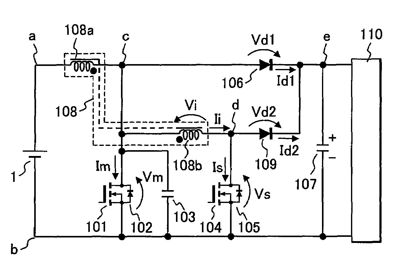
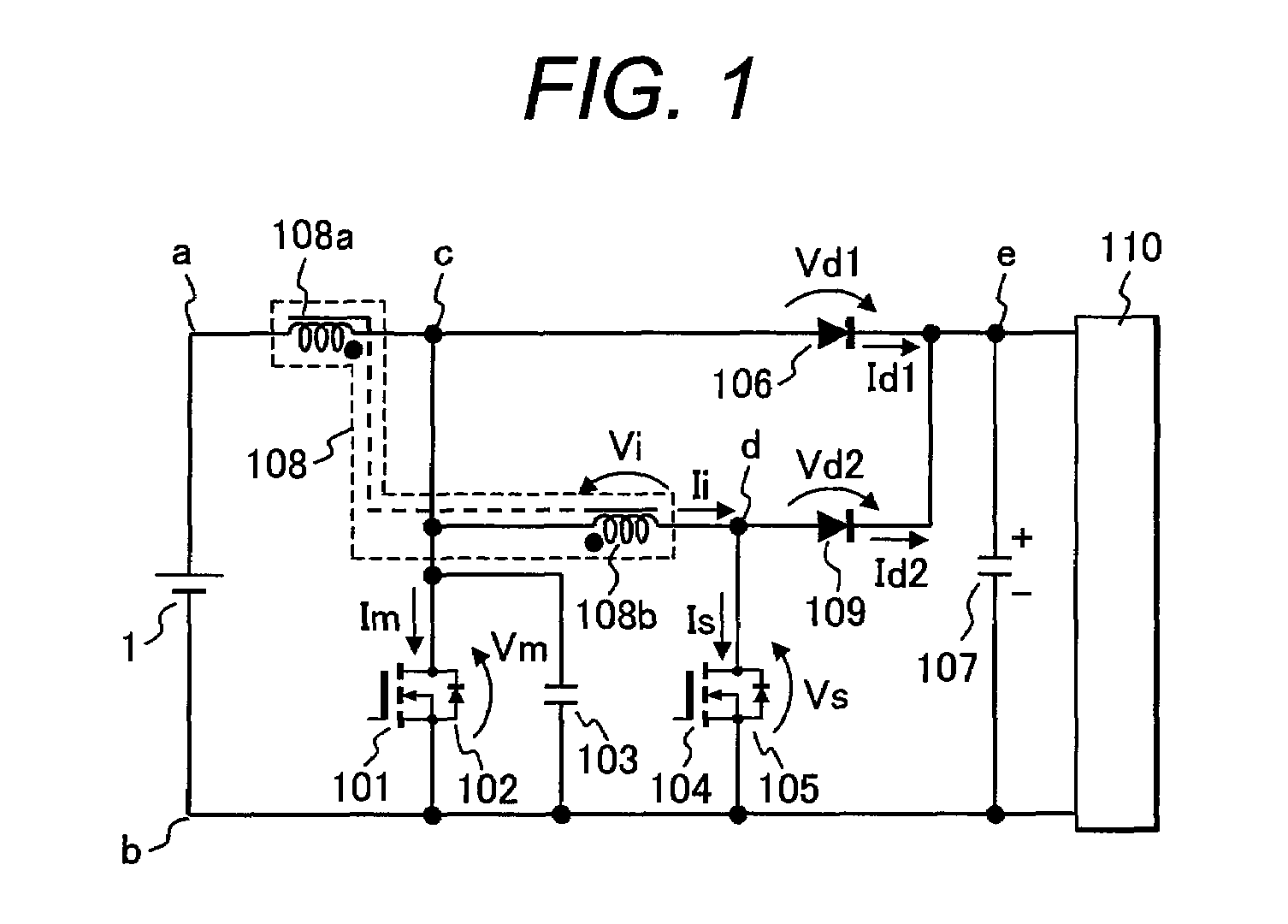
[0035]FIG. 1 is a circuitry diagram of a DC-DC converter in a first embodiment of the invention. This embodiment is a boost soft switching DC-DC converter that makes it possible to obtain an output voltage higher than input voltage.
[0036]Hereafter, description will be given to the circuitry in FIG. 1. First, a direct-current power source 1 is connected with a series circuit of a main inductor 108a and MOSFET 101 as a main switching element. This main MOSFET 101 is connected in inverse parallel with a diode 102. To take out output voltage, a series circuit of a main diode 106 and an output capacitor 107 is connected between the ends c and b of the main MOSFET 101. The ends of this output capacitor 107 are the output terminals of the DC-DC converter and are connected with a load 110.
[0037]Above is the description of the positional configuration of a common DC-DC converter and an auxiliary circuit of the invention is connected thereto.
[0038]The auxiliary circuit is obtained by: connect...
second embodiment
[0062]FIG. 5 is a circuitry diagram of a DC-DC converter having a detecting means and a control circuit in a second embodiment of the invention. This embodiment is also a boost soft switching DC-DC converter that makes it possible to obtain an output voltage higher than input voltage. In FIG. 5, the same components as in FIG. 1 will be marked with the same reference numerals and the description thereof will be omitted.
[0063]Description will be given to a difference of the DC-DC converter in FIG. 5 from that in FIG. 1. In FIG. 5, the direct-current power source 1 in FIG. 1 is comprised of: an alternating-current power source 2; a filter circuit comprised of an inductor 3 and a capacitor 4; a rectifying circuit 5; and a low-pass filter comprised of an inductor 6 and a capacitor 7. That is, the alternating-current voltage of the alternating-current power source 2 is full wave-rectified at the rectifying circuit 5 through the filter circuit comprised of the inductor 3 and the capacitor ...
third embodiment
[0069]FIG. 6 is a circuitry diagram of a DC-DC converter in a third embodiment of the invention. This embodiment is a buck soft switching DC-DC converter that makes it possible to obtain an output voltage lower than input voltage. In FIG. 6, the same components as in FIG. 1 will be marked with the same reference numerals and the description thereof will be omitted.
[0070]Description will be given to the circuitry of the DC-DC converter in FIG. 6. The direct-current power source 1 is connected with a series circuit of a main MOSFET 601 and a main diode 606; and the main MOSFET 601 is connected in inverse parallel with a diode 602 and in parallel with a snubber capacitor 603. Between the ends g and b of the main diode, a series circuit of a main inductor 607a and the output capacitor 107 is connected and the ends of the output capacitor 107 are connected to the load 110. Between the ends a and g of the main MOSFET 601, a series circuit of an auxiliary MOSFET 604 and an auxiliary induct...
PUM
 Abstract
Description
Claims
Application Information
 - R&D
- Intellectual Property
- Life Sciences
- Materials
- Tech Scout
- Unparalleled Data Quality
- Higher Quality Content
- 60% Fewer Hallucinations
Browse by: Latest US Patents, China's latest patents, Technical Efficacy Thesaurus, Application Domain, Technology Topic, Popular Technical Reports.
© 2025 PatSnap. All rights reserved.Legal|Privacy policy|Modern Slavery Act Transparency Statement|Sitemap|About US| Contact US: help@patsnap.com


