Fast-locking bang-bang PLL with low ouput jitter

a phase detector and fast lock technology, applied in the field of phaselocked loops, can solve the problems of low output jitter, analog pd has the disadvantage of only giving information on the mathematical sign or polarity of the phase error rather than on the signed magnitude, and achieves the effect of improving jitter (phase noise) performance in lock, fast lock times, and low cos

Active Publication Date: 2012-06-19
NXP BV
View PDF10 Cites 9 Cited by
  • Summary
  • Abstract
  • Description
  • Claims
  • Application Information

AI Technical Summary

Benefits of technology

[0009]It is therefore an object of the present invention to provide a simple and fast-locking bang-bang PLL with low output jitter, namely to provide a simple digital PLL able to achieve fast lock times while improving jitter (phase noise) performance in lock.
[0017]Thereby, the circuit can detect a repeating value or string of single-bit data of same polarity, and increase its output magnitude based on the reaction level in a significantly faster manner than with a circuit comprising only a single-bit phase detector.
[0018]The single-bit phase detector may be a bang-bang phase detector. Thereby, the design of the circuit can be kept as simple as possible.
[0026]Moreover, the mapping may be made by setting a threshold of the count value, the threshold defining a dead zone corresponding to a zero value of the reaction level. Thereby, only the repeating value or string of single-bit data of same polarity greater in absolute value than the threshold can lead to a non-zero reaction level, which prevents any jitter (phase noise) from increasing once lock has been achieved, since short strings can still occur in that case.
[0027]Additionally, the mapping may be made by setting a maximum value of the reaction level. Thereby, the reaction level can be limited during phase-locking process for avoiding entering unstable regions.

Problems solved by technology

However, the BBPD has the disadvantage, in comparison to an analog PD, to give information only on the mathematical sign or polarity of the phase error rather than on the signed magnitude.
Thus, the BBPD suffers from a jitter versus frequency tracking range trade-off, such that a trade-off must be found between output jitter in the time domain (or phase noise in the frequency domain), and DPLL lock time.
Indeed, a small response to the BBPD output leads to low output jitter, but also causes long DPLL lock times. Reversely, fast locking by strongly responding to the BBPD output causes high jitter when in phase lock.
But apart from being slightly off in frequency, there is still no guarantee for phase lock at all, since the phase may be off by as much as 180 degrees.
Achieving phase lock may still take much time, especially when the reaction of the DPLL 100 to a measured phase error is small in order to obey the jitter (phase noise) specification for example.
However, the major drawback of the TDC is its inherent design, which is far more complex than the BBPD design.

Method used


Image

  • Fast-locking bang-bang PLL with low ouput jitter
  • Fast-locking bang-bang PLL with low ouput jitter
  • Fast-locking bang-bang PLL with low ouput jitter

Examples


first embodiment

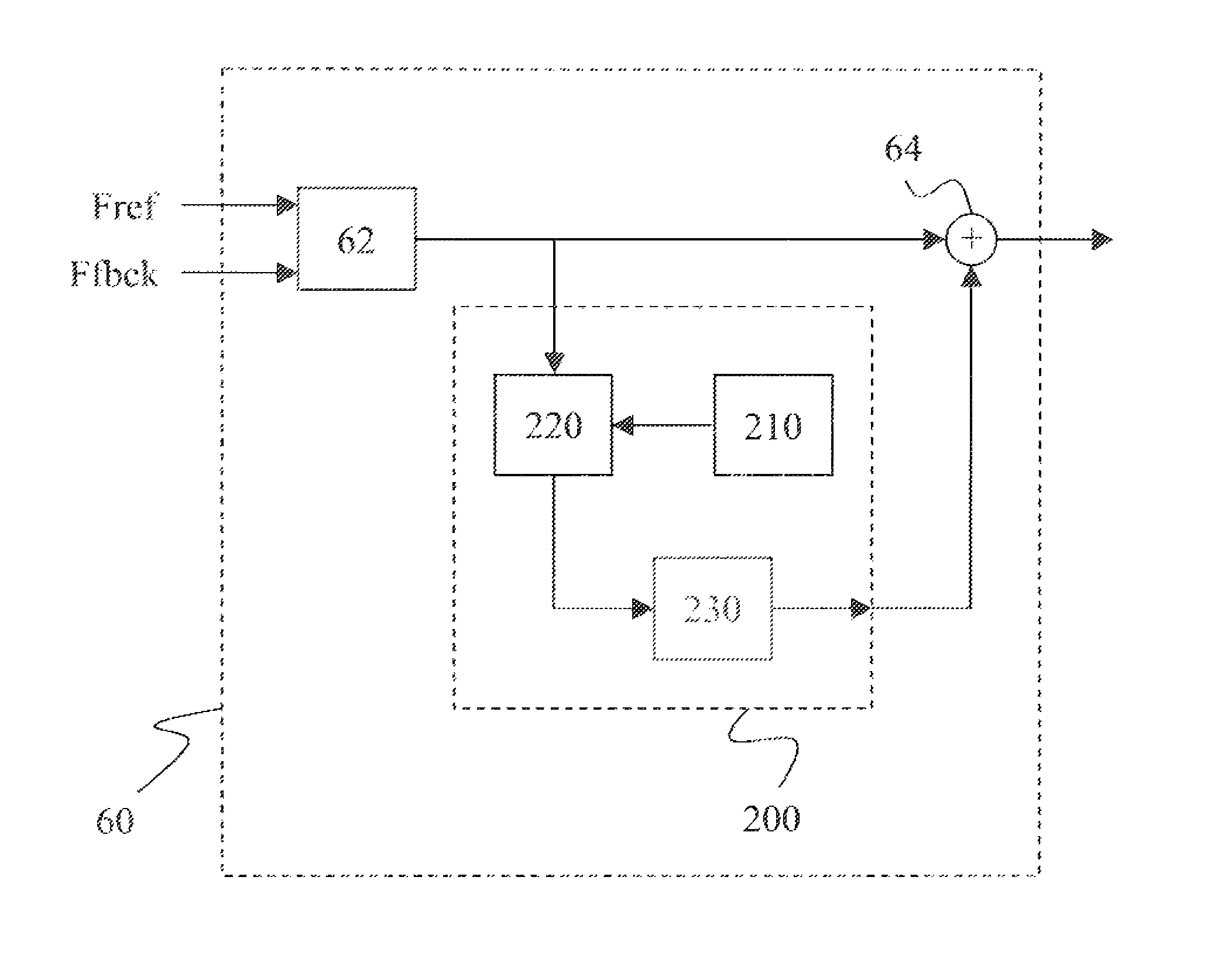
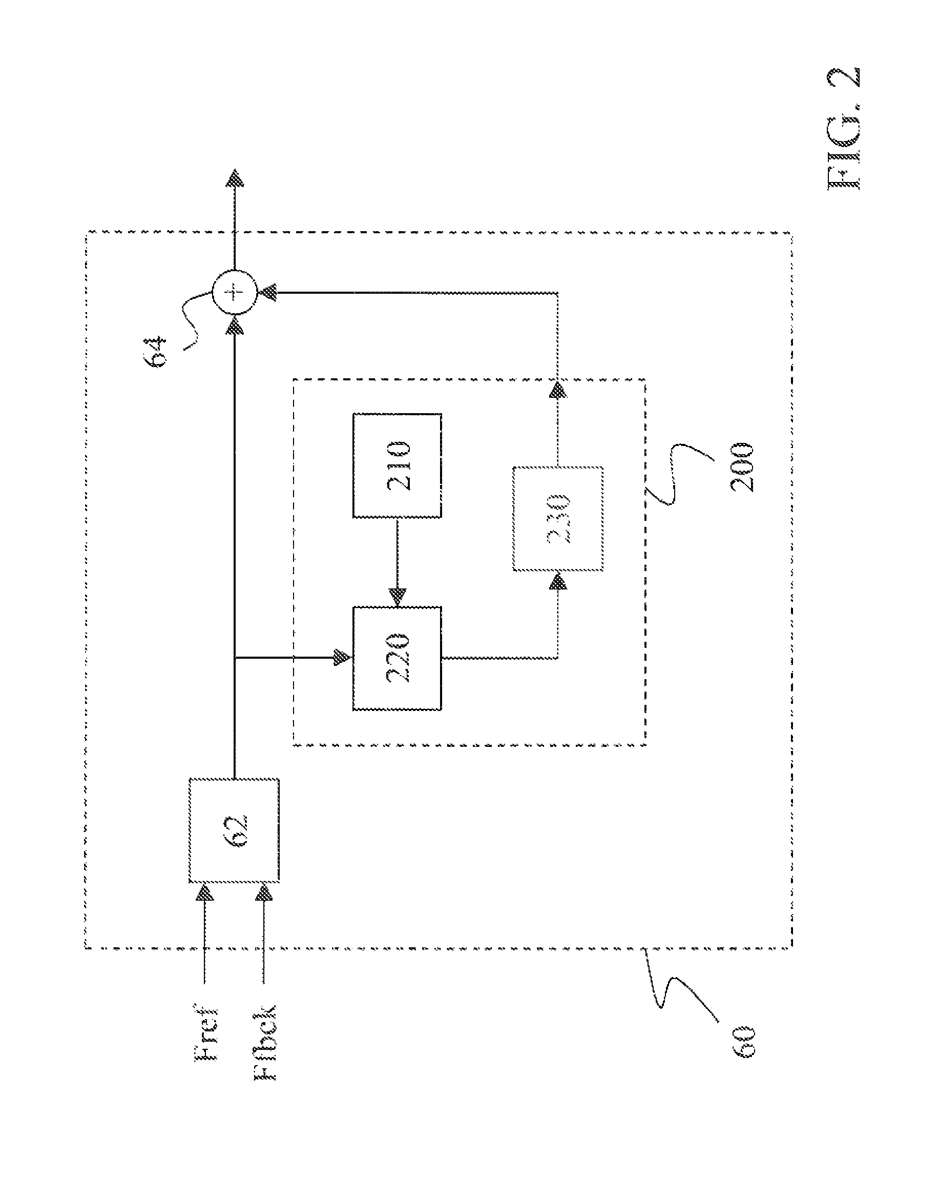
[0058]As depicted in FIG. 4a corresponding to the first embodiment, the sign detector 210 of FIG. 2 may be comprised of a delay element 211 and a comparator 212. In this case, the sign change at the BBPD output can be detected by the delay element 211, which delays the BBPD output by one reference clock period, together with the comparator 212, which compares the BBPD output and the delayed BBPD output and delivers the reset signal as a comparison result when a difference between those both outputs is detected.

second embodiment

[0059]As depicted in FIG. 4b corresponding to the second embodiment, the sign detector 210 of FIG. 2 may be comprised of a sign indicator 213 and a comparator 214. In this case, the sign change at the BBPD output can be detected by the sign indicator 213, which indicates the sign + or − of the count value output by the counter 220, together with the comparator 214, which compares the sign of the BBPD output with the sign of the count value and delivers the reset signal as a comparison result when a sign difference is detected.

third embodiment

[0060]As depicted in FIG. 4c corresponding to the third embodiment, the sign detector 210 of FIG. 2 may be comprised of a multiplier 215 and a comparator 216. In this case, the sign change at the BBPD output can be detected by the multiplier 215, which generates the mathematical product of the BBPD output with the count value, together with the comparator 216, which is configured to determine whether this mathematical product is less than zero (i.e. <0) and to deliver the reset signal if the response is affirmative, namely if the mathematical product is strictly negative.

[0061]As a variant to the third embodiment of FIG. 4c for detecting the sign change at the BBPD output, the comparator 216 may be replaced with another comparator 217 (not represented), which is configured to determine whether the mathematical product of the BBPD output and the count value is less than or equal to zero (i.e. ≦0) and to deliver the reset signal if the response is affirmative, namely if the mathematic...


PUM


Abstract

The present invention relates to a gigitaol phaselocked loop DPLL (300, 400) having a phase-to-digital P2D (60) with an enhanced bang-bang phase detector BBPD. Such a P2D (60) comprises a BBPD (62), an additional digital circuit (200) including a sign detector (210), a counter (220) and a mapping function (230), and a summer block (64). During the locking process, the BBPD (62) may-output a repeating value, namely a string of data bits of same polarity value either “+1” or “−1”. The polarity sign is detected by the sign detector (210), and the data string length is determined by the counter (220) that is reset to zero whenever the BBPD output changes sign. The mapping function (230) is configured for mapping the data string length in input to the phase correction level in output Its output is added to that of the BBPD (62) through the summer block (64), such that the phase correction level is increased to enhance the locking process whenever a data string is detected.

Description

FIELD OF THE INVENTION[0001]The present invention relates to the field of phase-locked loops, and more particularly to digital phase-locked loops with a bang-bang phase detector.BACKGROUND OF THE INVENTION[0002]Since the first phase-locked loop (PLL) designed in the 1930s for use in radio receivers, the phase locking concept has been applied to many applications ranging from generating clock signals in microprocessors to synthesizing frequencies. A conventional analog PLL is basically an oscillator whose frequency is locked onto some frequency component of an input signal. In the forward path, a phase detector (PD) compares the phase of the input signal to the phase of an output signal, and generates an output that is proportional to the phase difference. The output of the PD is filtered by an analog loop filter and then used to control the frequency of a voltage-controlled oscillator (VCO). An optional divider can be used in the feedback path for frequency multiplication. Through t...

Claims


Application Information

Patent Timeline
Patent Type & Authority Patents(United States)
IPC IPC(8): H03L7/06
CPCH03L7/085H03L7/091
Inventor VAN DE BEEK, REMCO CORNELIS HERMAN
Owner NXP BV
Why Eureka
Try Eureka