
Rapid, spatial-data viewing and manipulating including data partition and indexing

a spatial data and data viewing technology, applied in wave based measurement systems, instruments, reradiation, etc., can solve the problems of system running close to the limits of practical data collection and storage, format conversion generally takes significantly longer than collection time, and the data is typically a time-consuming process

Active Publication Date: 2012-06-19
LEICA GEOSYSTEMS AG
View PDF4 Cites 11 Cited by
  • Summary
  • Abstract
  • Description
  • Claims
  • Application Information

AI Technical Summary

Benefits of technology

The patent describes a method for quickly displaying and manipulating a point cloud of three-dimensional data collected from a laser scan. The method involves determining a partition structure for the data, adding data to memory, and storing it to form a leaf block when it reaches a predetermined capacity. The method also includes using a laser-measurement device that collects data with a regular pattern in two dimensions and writing a block of data to disk before establishing an index based on its three-dimensional attributes. The index allows for spatial queries to be performed on the data. The patent also describes a computer program that implements this method. The technical effects of this patent include improved efficiency and accuracy in processing and manipulating point cloud data, as well as improved data management and analysis.

Problems solved by technology

But using the data from three-dimensional (“3D”) laser scanners is typically a time-consuming process.
Given that disk write speeds are roughly 30 MB / see, the system already runs close to the limits of practical data collection and storage.
As such, this format conversion generally takes significantly longer than the collection time.

Method used


Image

  • Rapid, spatial-data viewing and manipulating including data partition and indexing
  • Rapid, spatial-data viewing and manipulating including data partition and indexing
  • Rapid, spatial-data viewing and manipulating including data partition and indexing

Examples


Embodiment Construction

[0020]The principles of the embodiments described herein describe the structure and operation of several examples used to illustrate the present invention. It should be understood that the drawings are diagrammatic and schematic representations of such example embodiments and, accordingly, are not limiting of the scope of the present invention, nor are the drawings necessarily drawn to scale. Well-known devices and processes have been excluded so as not to obscure the discussion in details that would be known to one of ordinary skill in the art.

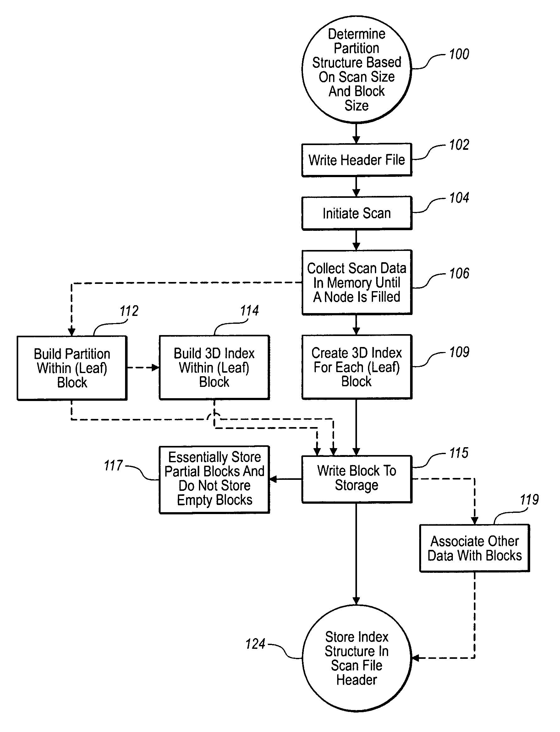
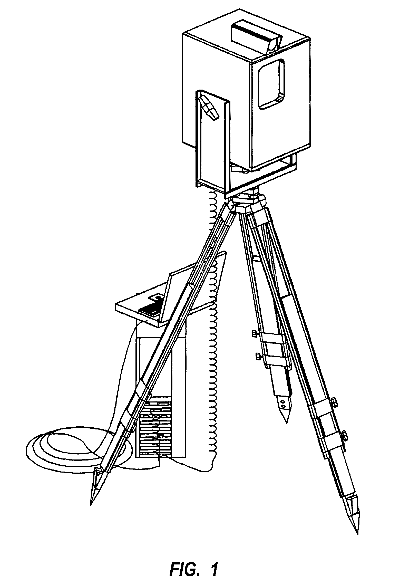
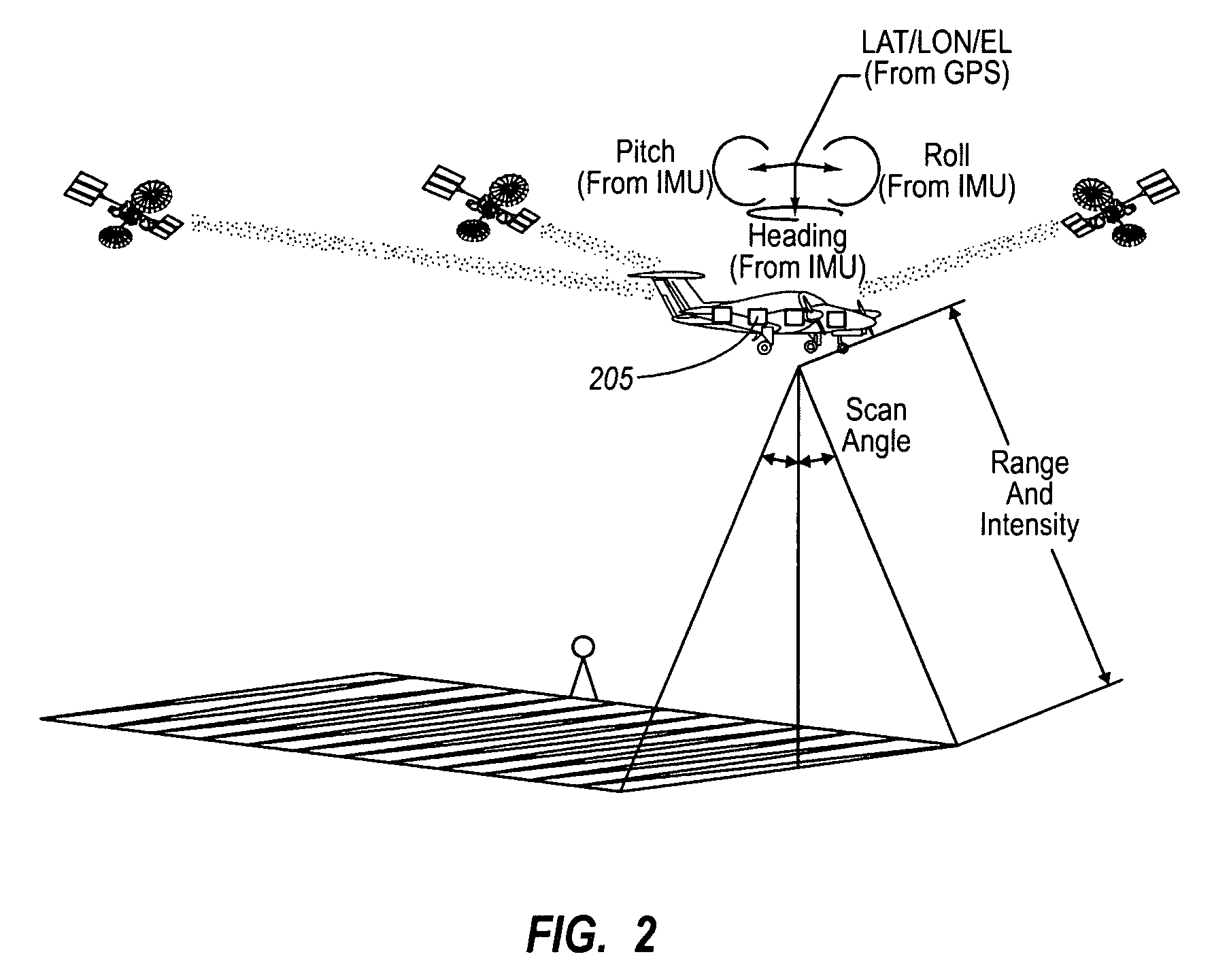
[0021]The principles of the present invention generally relate to a laser scanner, aerial LIDAR or other high-density, distance-measuring laser system and an associated computer that processes the data collected by the laser system. The computer determines a data partition structure and stores that structure as a header file for the scan even before data is collected. As the scan progresses, the computer collects data points until a predeterm...


PUM


Abstract

A high-density, distance-measuring laser system and an associated computer that processes the data collected by the laser system. The computer determines a data partition structure and stores that structure as a header file for the scan before data is collected. As the scan progresses, the computer collects data points until a predetermined threshold is met, at which point a block of data consisting of the data points up to the threshold is written to disk. The computer indexes each data block using all three coordinates of its constituent data points using, preferably, a flexible index, such as an R-tree. When a data block is completely filled, it is written to disk preferably with its index and, as a result, each data block is ready for access and manipulation virtually immediately after having been collected. Also, each data block can be independently manipulated and read from disk.

Description

CROSS-REFERENCE TO RELATED APPLICATIONS[0001]This application claims the benefit of U.S. Provisional Application No. 60 / 968,948 filed Aug. 30, 2007, which is incorporated herein by reference in its entirety.BACKGROUND[0002]Laser distance-measuring systems measure space to such a high degree of measurement density that the resultant mass of points, often called a point cloud, can appear as a coherent scene in the manner of a pointillist painting. Systems meeting this description include the laser scanner described in U.S. Pat. No. 5,988,862, the disclosure of which is hereby incorporated by reference, the Leica HDS6000 laser scanner from Leica Geosystems HDS, LLC, of San Ramon, Calif., or other LIDAR systems—such as the airborne LIDAR system disclosed in U.S. patent application Ser. No. 11 / 397,246 filed Apr. 4, 2006, and incorporated herein by reference. Each of these systems produce point clouds or sets of echoes, which are data sets representing points whose position and distance a...

Claims


Application Information

Patent Timeline
Patent Type & Authority Patents(United States)
IPC IPC(8): G06K9/46G06F7/00G06F17/30
CPCG01C15/002G01S17/89
Inventor WHEELER, MARK DAMONSCHWARZ, BARRY JOELBUKOWSKI, RICHARD WILLIAMWU, MINGHUA
Owner LEICA GEOSYSTEMS AG
Learn More