
Autonomous unmanned underwater vehicle with buoyancy engine

a technology of autonomous underwater vehicles and buoyancy engines, which is applied in the field of autonomous underwater vehicles, can solve the problems that the conventional underwater glider with a conventional buoyancy engine may be inadequate in some situations, and achieve the effect of improving the performance of the auv

Inactive Publication Date: 2012-06-26
CONSOLIDATED OCEAN TECH INC +1
View PDF31 Cites 71 Cited by
  • Summary
  • Abstract
  • Description
  • Claims
  • Application Information

AI Technical Summary

Benefits of technology

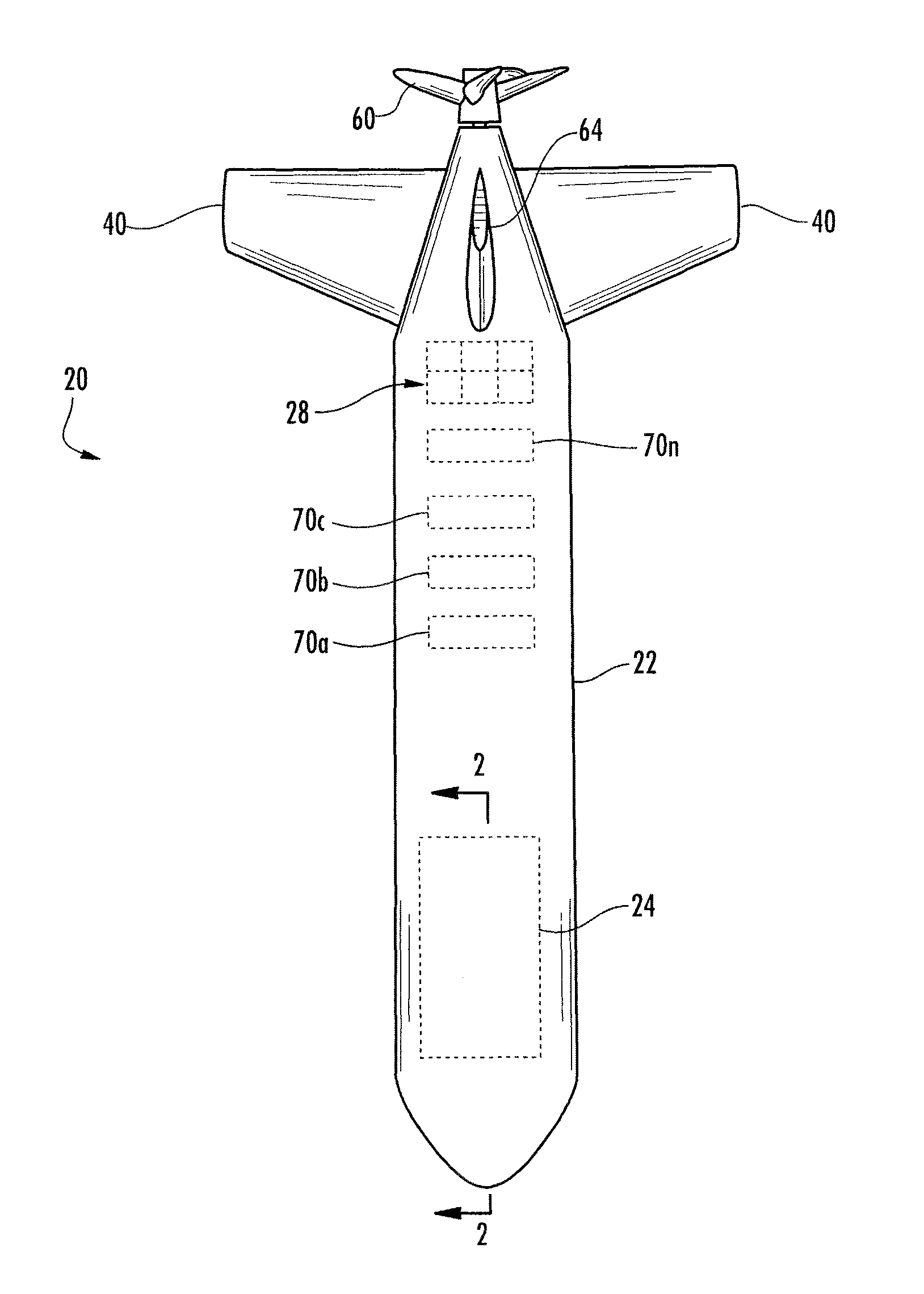
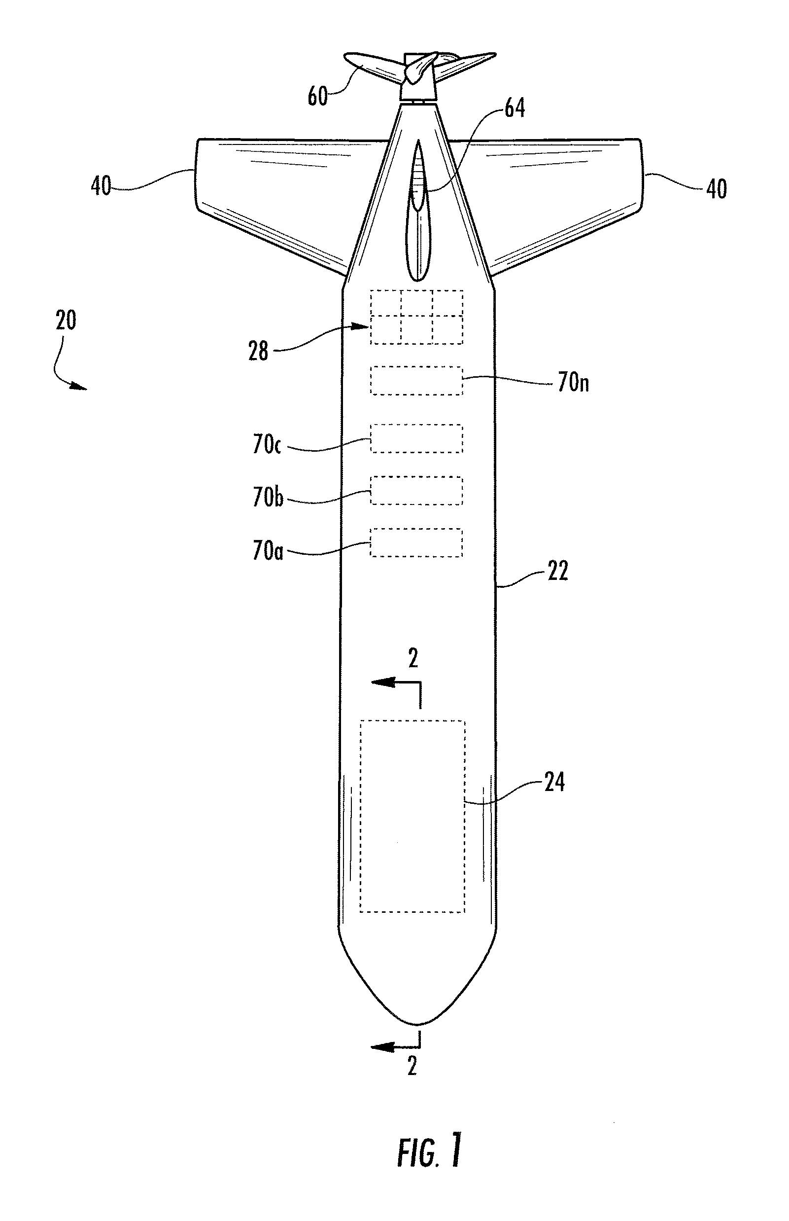
[0003]In accordance with one aspect of this disclosure, an autonomous unmanned underwater vehicle (“AUV”) includes a controller, a buoyancy engine, a rotary propulsion system and at least one pitch control surface. The buoyancy engine is for alternately ingesting and expelling ambient water to change the mass of the AUV and thereby cause the AUV to alternately descend and ascend in the water. The pitch control surface is for causing the AUV to move forward while alternately descending and ascending in the water. The rotary propulsion system includes a motor for rotating a rotary agitator (e.g., a propeller or an impeller) in the water to provide thrust. The controller is operative for responsively, automatically switching between at least glider and rotary propulsion modes. In the glider mode, the buoyancy engine and the pitch control surface cooperate to cause the AUV to move forward while alternately descending and ascending. In the rotary propulsion mode, the rotary propulsion system causes the AUV to move forward. The automatic switching between the modes may enhance performance of the AUV.

Problems solved by technology

A conventional underwater glider with a conventional buoyancy engine may be inadequate in some situations.

Method used


Image

  • Autonomous unmanned underwater vehicle with buoyancy engine
  • Autonomous unmanned underwater vehicle with buoyancy engine
  • Autonomous unmanned underwater vehicle with buoyancy engine

Examples


first embodiment

[0016]Initially, an autonomous unmanned underwater vehicle (“AUV”) 20 of the first embodiment is described. A general discussion of the components of the AUV 20 is followed by a general discussion of how the AUV 20 may operate, and thereafter there is a more specific discussion of the components of the AUV 20, followed by a more specific discussion of operation of the AUV 20.

[0017]FIG. 1 is a schematic top plan view of the AUV 20. In FIG. 1, some of the AUV's internal components, which are typically hidden from view, are shown in dashed lines. As shown in FIG. 1, the AUV has a body including a cylindrical hull 22 with a rounded front end and a tapered rear end. Any other suitably shaped body / hull may be used.

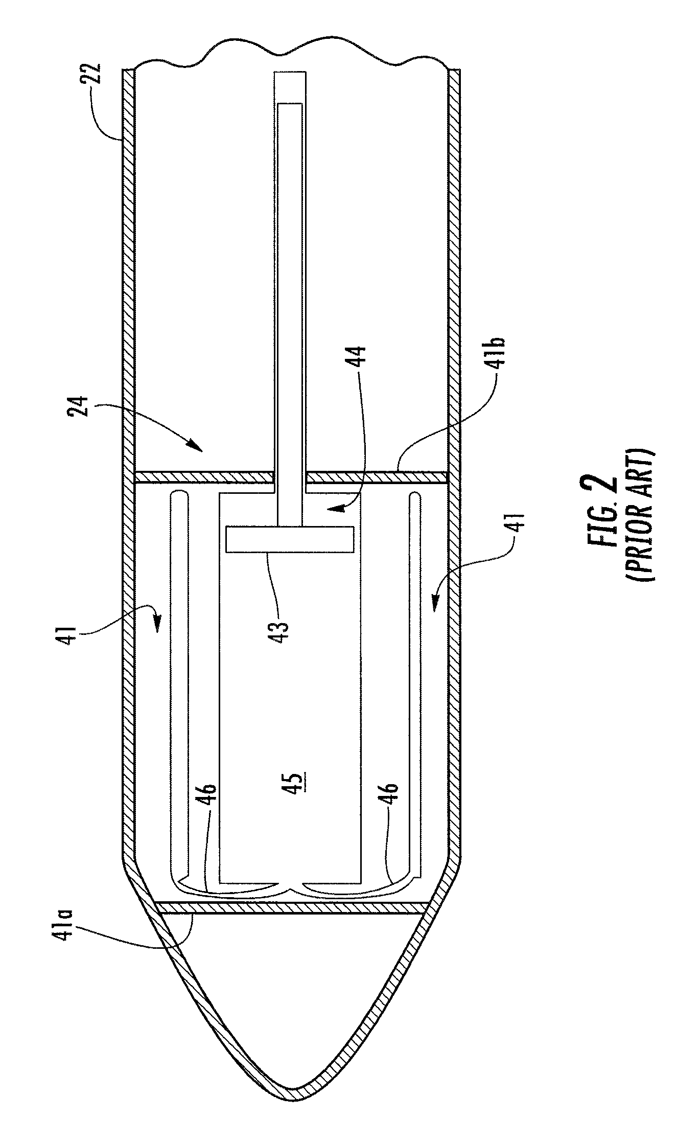
[0018]FIGS. 2 and 3 are schematic cross-sectional views of a forward portion of the AUV 20, with the cross-sections taken substantially along line 2-2 of FIG. 1. FIGS. 2 and 3 schematically show portions of one of the internal component of the AUV 20, namely a portion of a buoya...

second embodiment

[0019]The buoyancy engine 24 that is schematically, partially shown in FIGS. 2 and 3 is of a type that is typically located in, or proximate to, the nose (e.g., front end) of the AUV 20, and that causes a change in the center of gravity of the AUV while the buoyancy engine is operating. A variety of different buoyancy engines may be used at different locations within the AUV 20. For example, FIG. 13 illustrates another buoyancy engine that is discussed in greater detail below, in accordance with this disclosure. For example and as discussed in greater detail below, it is optional for the buoyancy engine of the AUV 20 to cause a change in the center of gravity of the AUV.

[0020]FIG. 4 is a schematic, perspective, partially cut-away view of a rear portion of the AUV 20. FIG. 4 schematically shows additional internal components of the AUV 20, namely internal components of a rotary propulsion system 26 and a steering system 27 that has fins 40, 64 or other suitable control surfaces. In a...


PUM


Abstract

An autonomous unmanned underwater vehicle (“AUV”) includes a body, a controller, a buoyancy engine, a rotary propulsion system and pitch control surface(s). The buoyancy engine is for alternately ingesting and expelling ambient water to change the mass of the AUV and thereby cause the AUV to alternately descend and ascend in the water. The pitch control surface(s) are for causing the AUV to move forward while alternately descending and ascending in the water. The rotary propulsion system includes a motor for rotating a propeller in the water to provide thrust. The controller is operative for responsively, automatically switching between at least the glider and rotary propulsion modes. In the glider mode, the buoyancy engine and the pitch control surface(s) are cooperative for causing the AUV to move forward while alternately descending and ascending. In the rotary propulsion mode, the rotary propulsion system is operative for causing the AUV to move forward.

Description

TECHNICAL FIELD[0001]The present disclosure relates to unmanned underwater vehicles and, more particularly, to an autonomous unmanned underwater vehicle that may be powered by a buoyancy engine.BACKGROUND[0002]An underwater glider is a type of autonomous unmanned underwater vehicle (“AUV”) that is powered by a buoyancy engine. The buoyancy engine is carried by the glider and typically includes a motor that is operative for changing the effective volume of a chamber, so that the chamber alternately ingests and expels ambient water to change the mass of the glider, so that the glider alternately ascends and descends. Conventional gliders typically include hydrodynamic wings for causing the AUV to move forward while alternately descending and ascending in the water. A conventional underwater glider with a conventional buoyancy engine may be inadequate in some situations.BRIEF SUMMARY[0003]In accordance with one aspect of this disclosure, an autonomous unmanned underwater vehicle (“AUV”...

Claims


Application Information

Patent Timeline
IPC IPC(8): B63G8/14
CPCB63G8/14B63G2008/002
Inventor TUREAUD, THOMAS F.HUMPHREYS, DOUGLAS E.
Owner CONSOLIDATED OCEAN TECH INC
Learn More