Abrasive compacts

a technology of abrasive compacts and compacts, which is applied in the field of abrasive compacts, can solve the problems of reducing the wear resistance of abrasive compacts, and brittleness, so as to improve the impact resistance and fatigue resistance, and improve the wear resistance of finer grained materials. the effect of the effect of the quality of the material

Active Publication Date: 2012-06-26
ELEMENT SIX TRADE MARKS LTD +1
View PDF15 Cites 4 Cited by
  • Summary
  • Abstract
  • Description
  • Claims
  • Application Information

AI Technical Summary

Benefits of technology

[0023]The invention further provides a method of manufacturing an abrasive compact, including the steps of subjecting a mass of ultrahard abrasive particles in the presence of a binder phase to conditions of elevated temperature and pressure suitable for producing an abrasive compact, the method being characterized by the mass of ultrahard particles having at least three different average particle sizes, which are provided in suitable quantities and relative average particle sizes as to maximize the average size of the binder pools of the sintered compact.

Problems solved by technology

Abrasive compacts tend to be brittle and in use they are frequently supported by being bonded to a cemented carbide substrate or support.
Typically, however, as these materials are made more wear resistant they become more brittle or prone to fracture.
Abrasive compacts designed for improved wear performance will therefore tend to have poor impact strength or reduced resistance to spalling.
This trade-off between the properties of impact resistance and wear resistance makes designing optimised abrasive compact structures, particularly for demanding applications, inherently self-limiting.
Additionally, because finer grained structures will typically contain more solvent / catalyst or metal binder, they tend to exhibit reduced thermal stability when compared to coarser grained structures.
This reduction in optimal behaviour for finer grained structures can cause substantial problems in practical application where the increased wear resistance is nonetheless required for optimal performance.
A specific problem with this solution is that the cobalt cemented carbide reduces the abrasion resistance of that portion of the ultrahard layer.
The problem with this general approach is that whilst it is possible to improve the wear and impact resistances when compared with either the coarse or fine-grained fraction alone, these properties still tend to be compromised i.e. the blend has a reduced wear resistance when compared to the finer grained material alone and a reduced impact resistance when compared to the coarser grained fraction.

Method used


Image

  • Abrasive compacts
  • Abrasive compacts

Examples


Embodiment Construction

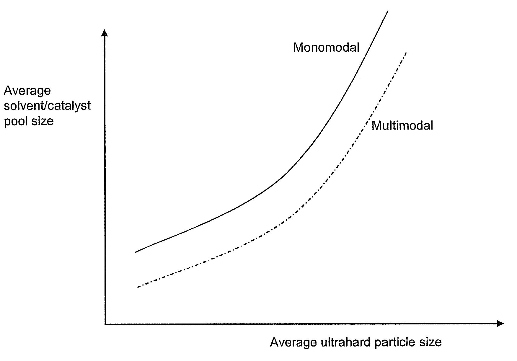
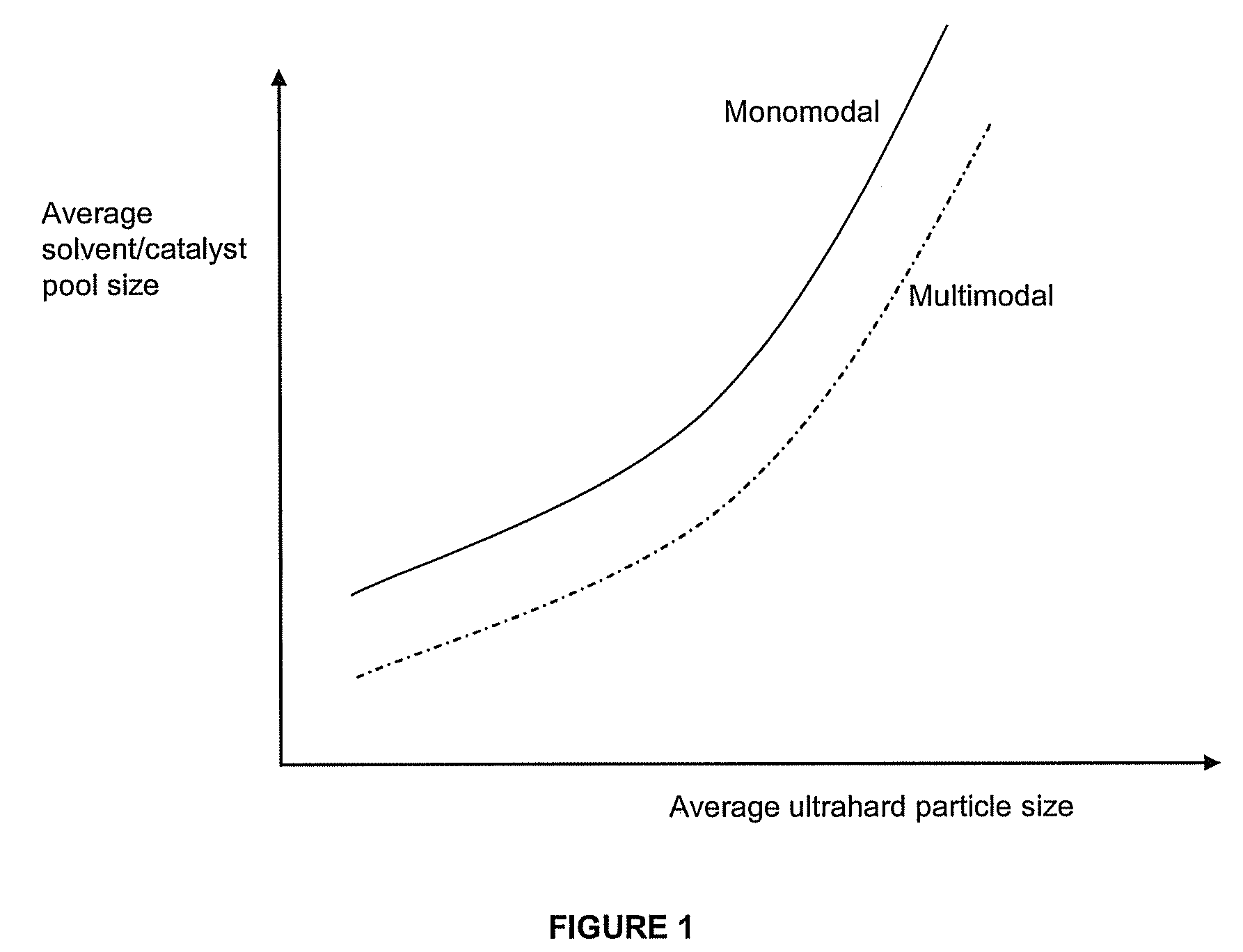
[0026]The present invention is directed to abrasive compacts, in particular ultrahard polycrystalline abrasive compacts, made under high pressure / high temperature conditions. The abrasive compacts are characterised in that the binder phase is distributed in such a manner as to maximize the average size of the pools in relation to the overall average grain size of the ultrahard particles, where the ultrahard particle distribution is multimodal.

[0027]The ultrahard abrasive particles may be diamond or cubic boron nitride, but are preferably diamond particles.

[0028]The ultrahard abrasive particle mass will be subjected to known temperature and pressure conditions necessary to produce an abrasive compact. These conditions are typically those required to synthesize the abrasive particles themselves. Generally, the pressures used will be in the range 40 to 70 kilobars and the temperature used will be in the range 1300° C. to 1600° C.

[0029]The abrasive compact, particularly for diamond comp...


PUM

PropertyMeasurementUnit
particle sizeaaaaaaaaaa

Abstract

An abrasive compact having at least a tri-modal particle size distribution, and a binder phase, define a plurality of interstices. The binder phase is distributed in the interstices to form binder pools that correspond substantially in average size to that of an ultrahard polycrystalline composite material having a monomodal particle size distribution and substantially the same overall average particle grain size.

Description

CROSS-REFERENCE TO RELATED APPLICATIONS[0001]This application is a National Stage of PCT / IB07 / 53001 filed Jul. 30, 2007 and claims the benefit of South African patent application 2006 / 06239 filed Jul. 31, 2006.BACKGROUND OF THE INVENTION[0002]This invention relates to abrasive compacts.[0003]Abrasive compacts are used extensively in cutting, milling, grinding, drilling and other abrasive operations. Abrasive compacts consist of a mass of ultrahard particles, typically diamond or cubic boron nitride, bonded into a coherent, polycrystalline conglomerate. The abrasive particle content of abrasive compacts is high and there is generally an extensive amount of direct particle-to-particle bonding or contact. Abrasive compacts are generally sintered under elevated temperature and pressure conditions at which the abrasive particle, be it diamond or cubic boron nitride, is crystallographically or thermodynamically stable.[0004]Some abrasive compacts may additionally have a second phase which...

Claims


Application Information

Patent Timeline
Patent Type & Authority Patents(United States)
IPC IPC(8): B24D3/02E21B10/36C09C1/68C09K3/14
CPCB24D3/06
Inventor TANK, KLAUSACHILLES, ROY DERRICK
Owner ELEMENT SIX TRADE MARKS LTD
Why Eureka
Try Eureka