
R—Fe—B rare earth sintered magnet and method for producing same

a rare earth, sintered magnet technology, applied in the direction of magnetic bodies, soldering devices, manufacturing tools, etc., can solve the problems of not being heated sufficiently by a normal resistance heating process, not easy to obtain the expected crystal structure, etc., to achieve the effect of reducing the remanence br and increasing the coercivity hcj

Active Publication Date: 2012-06-26
HITACHI METALS LTD
View PDF19 Cites 22 Cited by
  • Summary
  • Abstract
  • Description
  • Claims
  • Application Information

AI Technical Summary

Benefits of technology

The present invention relates to an R-Fe-B based rare-earth sintered magnet with high coercivity and remanence, and a method for producing it. The invention focuses on replacing a portion of the light rare-earth element in the magnet with a heavy rare-earth element to increase the coercivity without significantly decreasing the remanence. The invention also discusses adding a small amount of heavy rare-earth element to the magnet to improve the magnetocrystalline anisotropy and the coercivity of the magnet. The heavy rare-earth element can be distributed near the grain boundary of the magnet to improve the magnetocrystalline anisotropy and nucleation of reverse magnetic domains. The invention also describes methods for depositing a metal or alloy containing a heavy rare-earth element on the surface of the magnet to increase the coercivity without decreasing the remanence.

Problems solved by technology

For that reason, it is not easy to obtain the expected crystal structure.
However, Dy has a boiling point of 2,560° C. According to Patent Document No. 4, Yb with a boiling point of 1,193° C. should be heated to a temperature of 800° C. to 850° C. but could not be heated sufficiently by a normal resistance heating process.

Method used


Image

  • R—Fe—B rare earth sintered magnet and method for producing same
  • R—Fe—B rare earth sintered magnet and method for producing same
  • R—Fe—B rare earth sintered magnet and method for producing same

Examples


embodiment 1

Material Alloy

[0104]First, an alloy including 25 mass % to 40 mass % of a light rare-earth element RL, 0.6 mass % to 1.6 mass % of B (boron) and Fe and inevitably contained impurities as the balance is provided. A portion of B may be replaced with C (carbon) and a portion (50 at % or less) of Fe may be replaced with another transition metal element such as Co or Ni. For various purposes, this alloy may contain about 0.01 mass % to about 1.0 mass % of at least one additive element M that is selected from the group consisting of Al, Si, Ti, V, Cr, Mn, Ni, Cu, Zn, Ga, Zr, Nb, Mo, Ag, In, Sn, Hf, Ta, W, Pb and Bi.

[0105]Such an alloy is preferably made by quenching a melt of a material alloy by a strip casting process, for example. Hereinafter, a method of making a rapidly solidified alloy by a strip casting process will be described.

[0106]First, a material alloy with the composition described above is melted by an induction heating process within an argon atmosphere to make a melt of th...

embodiment 2

[0124]First, an alloy including 25 mass % to 40 mass % of rare-earth elements (0.1 mass % to 5.0 mass % of which is a heavy rare-earth element RH and the balance of which is a light rare-earth element RL), 0.6 mass % to 1.6 mass % of B (boron) and Fe and inevitably contained impurities as the balance is provided. A portion of B may be replaced with C (carbon) and a portion (50 at % or less) of Fe may be replaced with another transition metal element such as Co or Ni. For various purposes, this alloy may contain about 0.01 mass % to about 1.0 mass % of at least one additive element M that is selected from the group consisting of Al, Si, Ti, V, Cr, Mn, Ni, Cu, Zn, Ga, Zr, Nb, Mo, Ag, In, Sn, Hf, Ta, W, Pb and Bi.

[0125]In this manner, according to this preferred embodiment, 0.1 mass % to 5.0 mass % of heavy rare-earth element RH is added to the material alloy. Specifically, a known R—Fe—B based rare-earth sintered magnet, including a light rare-earth element RL (which is at least one o...

embodiment 3

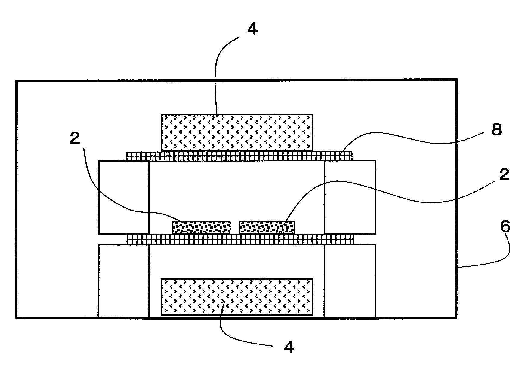
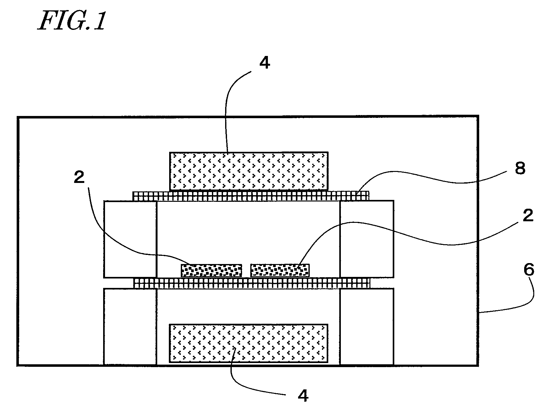
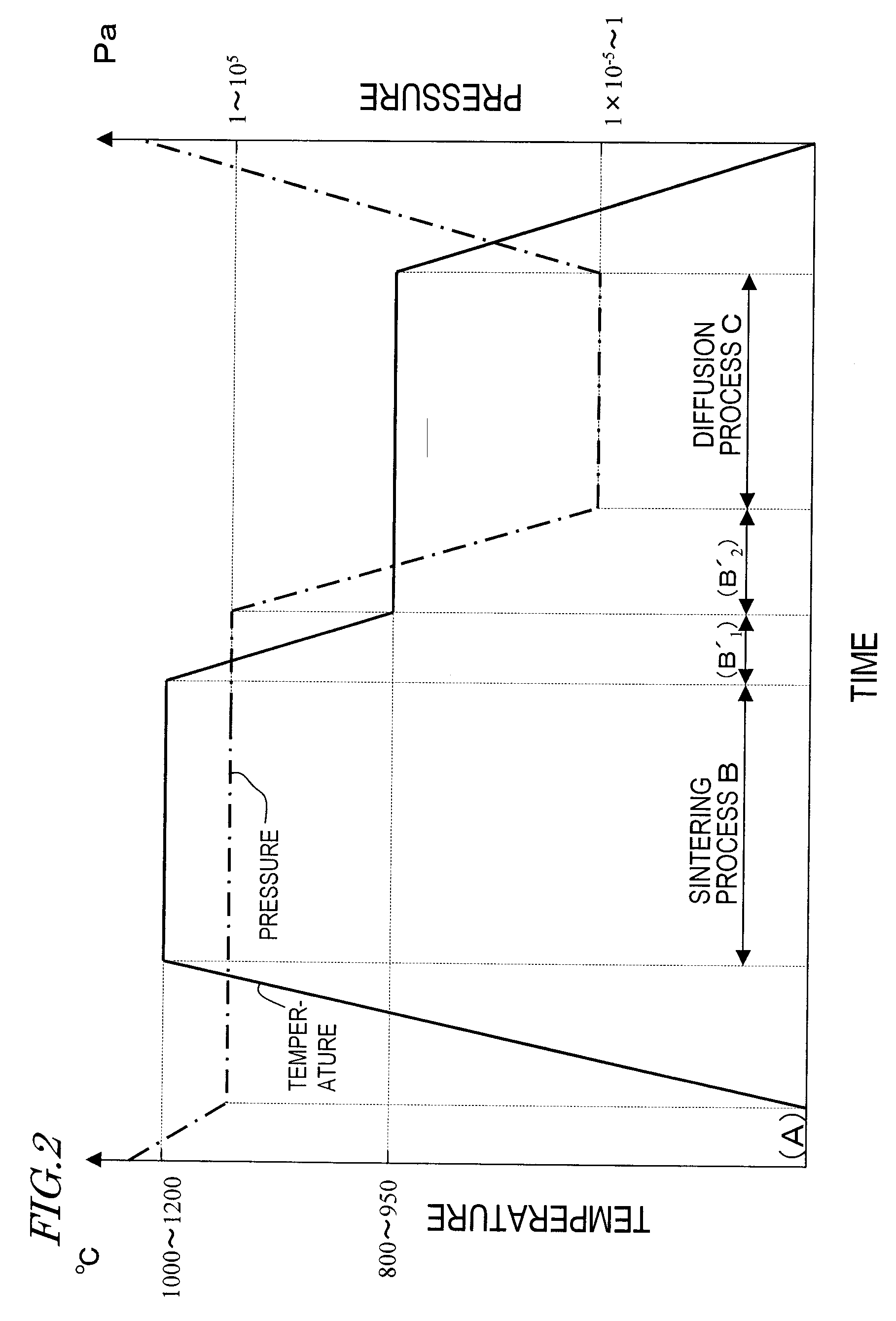
[0130]In a method of producing an R—Fe—B based rare-earth sintered magnet according to a third preferred embodiment of the present invention, the process step of sintering a compact of an R—Fe—B based rare-earth magnet powder and the process step of diffusing a heavy rare-earth element RH are performed continuously in the same processing chamber. More specifically, performed first is the process step (A) of arranging a compact of an R—Fe—B based rare-earth magnet powder, including a light rare-earth element RL (which is at least one of Nd and Pr) as a major rare-earth element R, in a processing chamber such that the compact faces a bulk body including a heavy rare-earth element RH, which is at least one element selected from the group consisting of Dy, Ho and Tb.

[0131]Next, the process step (B) of performing a sintering process in the processing chamber, thereby making an R—Fe—B based rare-earth sintered magnet body including crystal grains of an R2Fe14B type compound as a main phas...


PUM

PropertyMeasurementUnit
temperatureaaaaaaaaaa
pressureaaaaaaaaaa

Abstract

In a method for producing an R—Fe—B based rare-earth sintered magnet according to the present invention, first, provided is an R—Fe—B based rare-earth sintered magnet body including, as a main phase, crystal grains of an R2Fe14B type compound that includes a light rare-earth element RL, which is at least one of Nd and Pr, as a major rare-earth element R. Thereafter, the sintered magnet body is heated while a heavy rare-earth element RH, which is at least one element selected from the group consisting of Dy, Ho and Tb, is supplied to the surface of the sintered magnet body, thereby diffusing the heavy rare-earth element RH into the rare-earth sintered magnet body.

Description

TECHNICAL FIELD[0001]The present invention relates to an R—Fe—B based rare-earth sintered magnet including crystal grains of an R2Fe14B type compound (where R is a rare-earth element) as a main phase and a method for producing such a magnet. More particularly, the present invention relates to an R—Fe—B based rare-earth sintered magnet, which includes a light rare-earth element RL (which is at least one of Nd and Pr) as a major rare-earth element R and in which a portion of the light rare-earth element RL is replaced with a heavy rare-earth element RH (which is at least one element selected from the group consisting of Dy, Ho and Tb) and a method for producing such a magnet.BACKGROUND ART[0002]An R—Fe—B based rare-earth sintered magnet, including an Nd2Fe14B type compound phase as a main phase, is known as a permanent magnet with the highest performance, and has been used in various types of motors such as a voice coil motor (VCM) for a hard disk drive and a motor for a hybrid car an...

Claims


Application Information

Patent Timeline
Patent Type & Authority Patents(United States)
IPC IPC(8): H01F1/057
CPCB22F7/062H01F1/0577H01F41/0293Y10T428/12028B22F2998/10B22F2999/00B22F2009/044B22F9/04B22F3/02B22F3/10B22F2201/013B22F2202/05C22C38/005
Inventor YOSHIMURA, KOSHIMORIMOTO, HIDEYUKIODAKA, TOMOORI
Owner HITACHI METALS LTD
Learn More