Aircraft stabilizer system and methods of using the same

a stabilizer and helicopter technology, applied in the field of helicopters, can solve the problems of reducing the performance and efficiency of the helicopter, reducing the thrust force, and difficulty in maintaining the proper heading of the helicopter, and achieve the effects of improving performance, large thrust force, and small profil

Active Publication Date: 2012-07-03
BLR AEROSPACE
View PDF15 Cites 24 Cited by
  • Summary
  • Abstract
  • Description
  • Claims
  • Application Information

AI Technical Summary

Benefits of technology

[0006]At least some embodiments disclosed herein include an aircraft that has a stabilizer system for improved performance. The stabilizer system includes a vertical stabilizer with a relatively small profile, as viewed from the side, as compared to profiles of traditional stabilizers. The vertical stabilizer can allow a tail rotor of the aircraft to produce relatively large thrust forces for counteracting reaction torques. The stabilizer system may further include one or more airflow modifiers, such as strakes, mounted on a tail section of the aircraft. In some embodiments, the aircraft has a plurality of airflow modifiers that cooperate with the reduced profile vertical stabilizer to provide increased aircraft maneuverability.
[0008]In some embodiments, a stabilizer at a rearward end of a tail boom of an aircraft is retrofitted with a new trailing edge to reduce the size of the stabilizer. For example, a trailing edge of the stabilizer can have a gradually tapered V-shape as viewed from above. The V-shaped trailing edge is replaced with a new trailing edge having a different configuration. The new trailing edge can have a relatively round shape to reduce a chord length of at least a portion of the stabilizer. In some embodiments, the stabilizer is a vertically oriented fin-type stabilizer. The stabilizer can have an upper fin extending upwardly from the tail boom and a lower fin extending downwardly from the tail boom.
[0013]In some embodiments, a method of modifying an aircraft comprises providing a vertical stabilizer that includes a non-rounded trailing edge, such as a sharp V-shaped trailing edge. A portion of the vertical stabilizer has a first average chord length. The non-rounded trailing edge is replaced with a rounded trailing edge such that the portion of the vertical stabilizer has a second average chord length that is less than the first average chord length. In some embodiments, the second average chord length is less than 70%, 80%, 90%, or 95% of the first average chord length. In some embodiments, the non-rounded trailing edge is removed by cutting away a rearward portion of the vertical stabilizer. In other embodiments, the vertical stabilizer has a separate component that defines the non-rounded trailing edge. Various techniques can be used to remove the non-rounded trailing edge. That component can be conveniently separated from a main body of the vertical stabilizer.

Problems solved by technology

It may be difficult to maintain the proper heading of the helicopter because a reaction torque generated by rotation of the main lifting rotor tends to cause unwanted rotation of a fuselage of the helicopter.
Unfortunately, the vertically oriented stabilizer may block the airflow generated by the tail rotor resulting in a reduced thrust force, which may significantly reduce helicopter performance and efficiency.

Method used


Image

  • Aircraft stabilizer system and methods of using the same
  • Aircraft stabilizer system and methods of using the same
  • Aircraft stabilizer system and methods of using the same

Examples


Embodiment Construction

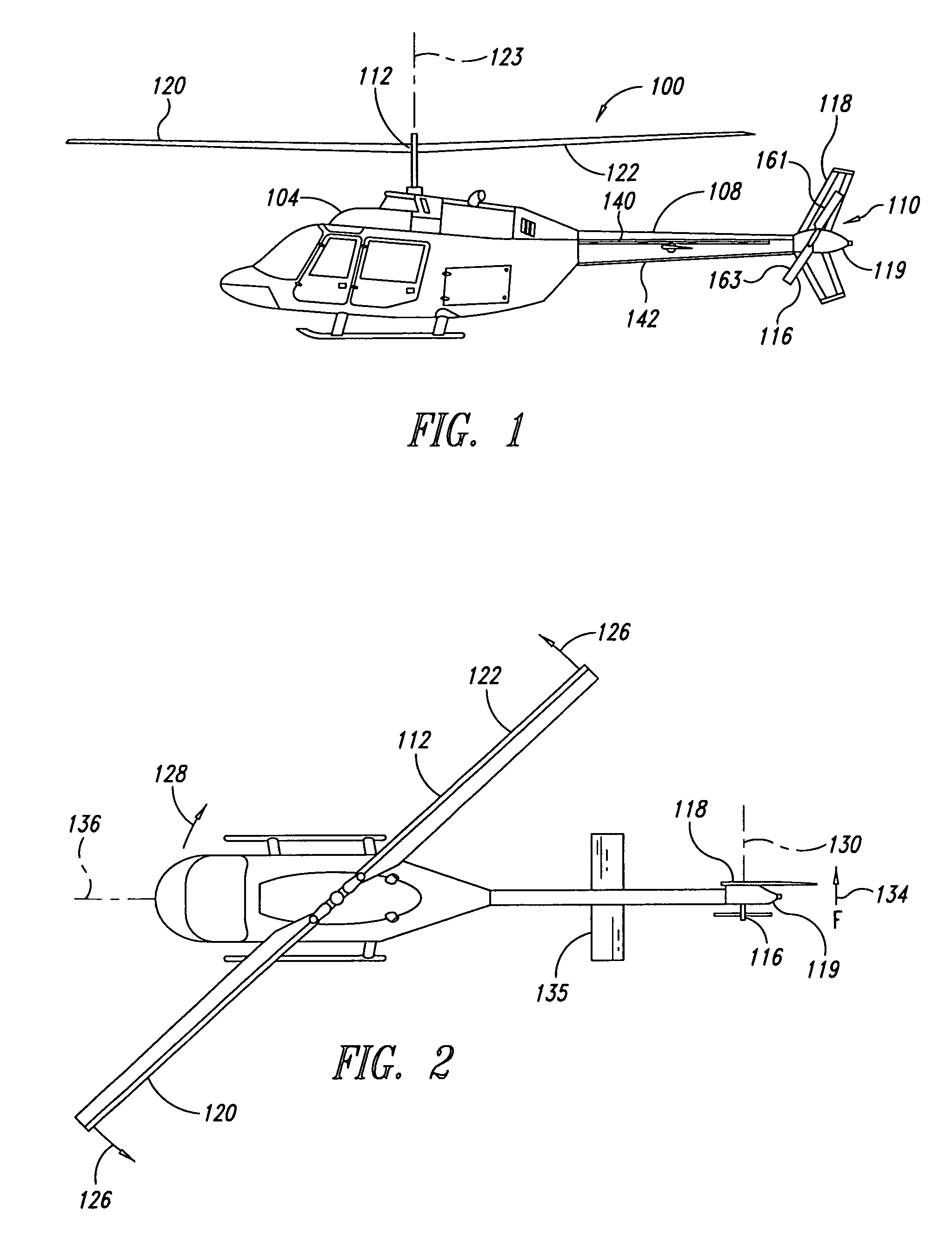
[0043]In the following description, certain specific details are set forth in order to provide a thorough understanding of various embodiments of the invention. However, one skilled in the art will understand that the invention may be practiced without these details. Stabilizing systems are disclosed in the context of tail sections of helicopters because they have particular utility in this context. However, the stabilizing systems can be incorporated into other types of aircraft in which aerodynamics is a significant consideration. Terms, such as “rear,”“front,”“rearward,”“forward,”“counter clockwise,”“clockwise,”“upward,” and “downward,” and variations thereof are used to describe the illustrated embodiments and are used consistently with the description of non-limiting exemplary applications. It will be appreciated, however, that the illustrated embodiments can be located or oriented in a variety of desired positions.

[0044]Unless the context requires otherwise, throughout the spe...


PUM

PropertyMeasurementUnit
angleaaaaaaaaaa
angleaaaaaaaaaa
angleaaaaaaaaaa

Abstract

An aircraft can include a tail section and a stabilizing system coupled to the tail section. The stabilizing system has a vertical stabilizer and at least one strake that cooperate to generate forces that compensate for a reaction torque generated by a main lifting rotor that produces lifting forces when the aircraft is in flight. Methods for improving aircraft performance include installing the at least one strake and retrofitting of a vertical stabilizer to increase thrust forces produced by a tail rotor.

Description

CROSS-REFERENCE TO RELATED APPLICATION[0001]This application claims the benefit under 35 U.S.C. §119(e) of U.S. Provisional Patent Application No. 60 / 930,233 filed May 14, 2007, which is incorporated herein by reference in its entirety.BACKGROUND[0002]1. Technical Field[0003]The present disclosure generally relates to aircraft with stabilizer systems, and more specifically to helicopters with stabilizer systems that alter the aerodynamics of the helicopter.[0004]2. Description of the Related Art[0005]Traditional single rotor helicopters have a main lifting rotor for providing a lifting force and a tail rotor for providing a laterally directed force used to adjust yaw alignment. Tail rotors are often positioned next to a vertically oriented stabilizer at a rearward end of a tail boom. It may be difficult to maintain the proper heading of the helicopter because a reaction torque generated by rotation of the main lifting rotor tends to cause unwanted rotation of a fuselage of the helic...

Claims


Application Information

Patent Timeline
Patent Type & Authority Patents(United States)
IPC IPC(8): B64C27/00
CPCB64C27/04B64C27/14Y10T29/4973Y10T29/49721Y10T29/49622B64C2027/8245
Inventor DESROCHE, ROBERT J.
Owner BLR AEROSPACE
Why Eureka
Try Eureka