
Relay driving circuit and battery pack using same

a relay driving circuit and battery pack technology, applied in relays, emergency power supply arrangements, secondary cells servicing/maintenance, etc., can solve the problems of increasing energy loss and heat generation, relay coils generating heat due, and known problems, so as to improve relay operation at the time of initiation of operation, reduce heat generation, and reduce relay driving current

Active Publication Date: 2012-07-03
PANASONIC CORP
View PDF20 Cites 11 Cited by
  • Summary
  • Abstract
  • Description
  • Claims
  • Application Information

AI Technical Summary

Benefits of technology

"The invention provides a relay driving circuit and battery pack that can reduce the current and heat generation of the relay while improving its reliability during initial operation. The circuit includes a relay, capacitor, switching portion, and control portion. The capacitor is charged by connecting the first terminal and the capacitor through the switching portion, and then the power supply and capacitor are connected to the coil of the relay to supply voltage to the coil. This results in a series circuit of the power supply and capacitor, which is connected to the coil of the relay. The circuit design reduces the current and heat generation during relay operation, improving its reliability. The battery pack includes the relay driving circuit and a battery connected in series to the relay. The technical effects of the invention include improved reliability and reduced heat generation during relay operation."

Problems solved by technology

However, when a relay is driven under constant voltage, the following problem is known to arise.
On the other hand, the relay coil generates heat due to losses which are the product of the resistance and the flowing current.
However, in the case of the technology of Patent Documents 1 and 2, because of the resistor connected in series with the relay coil, a loss occurs due to the product of the coil driving current and the resistance of the resistor, and in the case of the technology of Patent Document 3, because of the Zener diode connected in series with the relay coil, a loss occurs due to the product of the coil driving current and the Zener voltage of the Zener diode, so that there are the problems of increases in energy losses and heat generation.
And in the case of the technology of Patent Document 4, because two constant-voltage power supplies are necessary, there is the problem that the circuit scale is increased.
And in the case of the technology of Patent Document 5, there is the problem of the occurrence of radiation noise upon on / off control of the relay driving voltage.Patent Document 1: Japanese Patent Application Laid-open No.

Method used


Image

  • Relay driving circuit and battery pack using same
  • Relay driving circuit and battery pack using same
  • Relay driving circuit and battery pack using same

Examples


Embodiment Construction

[0026]Below, aspects of the invention are explained based on the drawings. Portions to which the same symbol is assigned the drawings are the same, and redundant explanations thereof are omitted.

[0027](First Aspect)

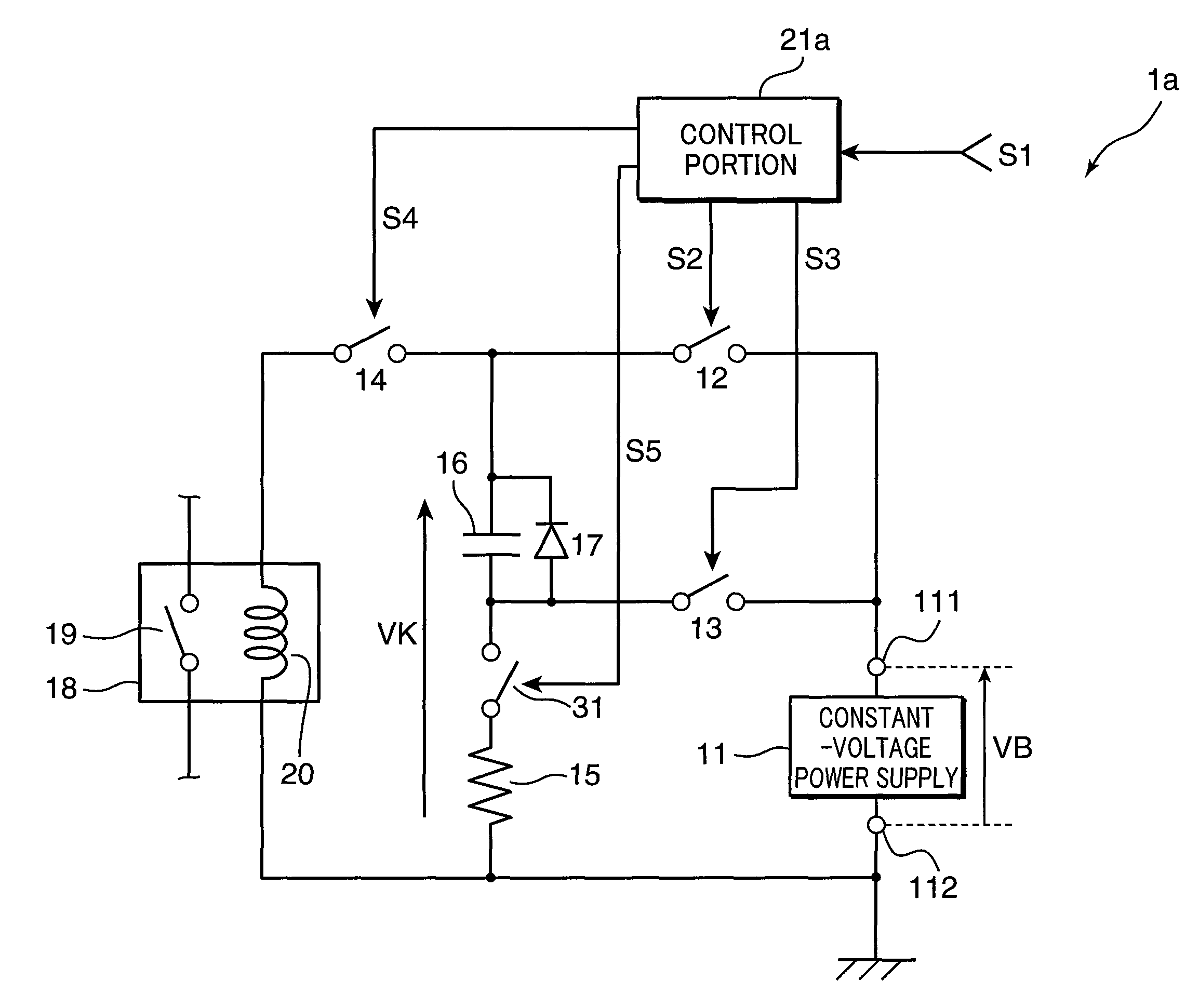
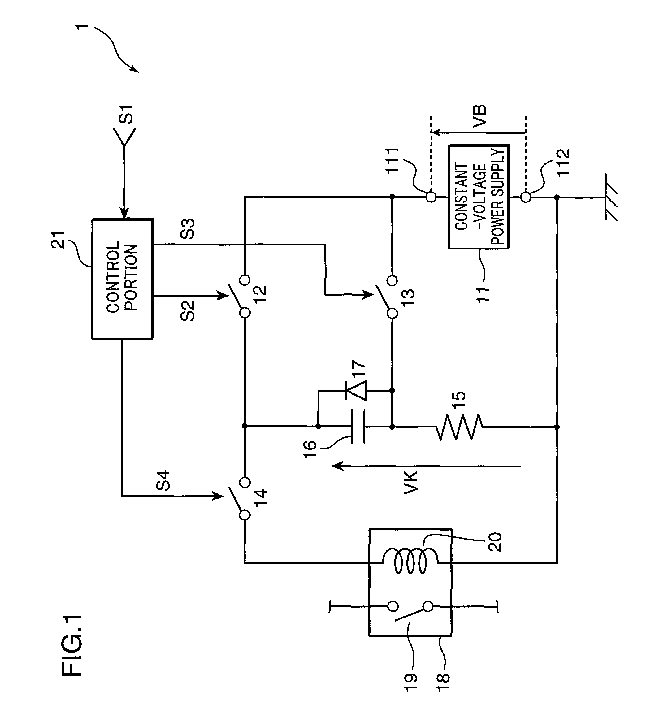
[0028]FIG. 1 shows an example of the configuration of the relay driving circuit of a first aspect of the invention. The relay driving circuit 1 shown in FIG. 1 comprises a constant-voltage power supply 11, terminal 111 (first terminal), terminal 112 (second terminal), switching element 12 (first switch portion), switching element 13 (second switch portion), switching element 14 (third switch portion), resistor 15, capacitor 16, diode 17, relay 18, and control portion 21.

[0029]The relay 18 comprises a relay contact 19 and a relay coil 20, and is for example to turn on and off the driving current for the load of a vehicle (for example, a driving motor or similar), or to open and close various current supply circuits. The switching elements 12, 13, 14 are for example transis...


PUM


Abstract

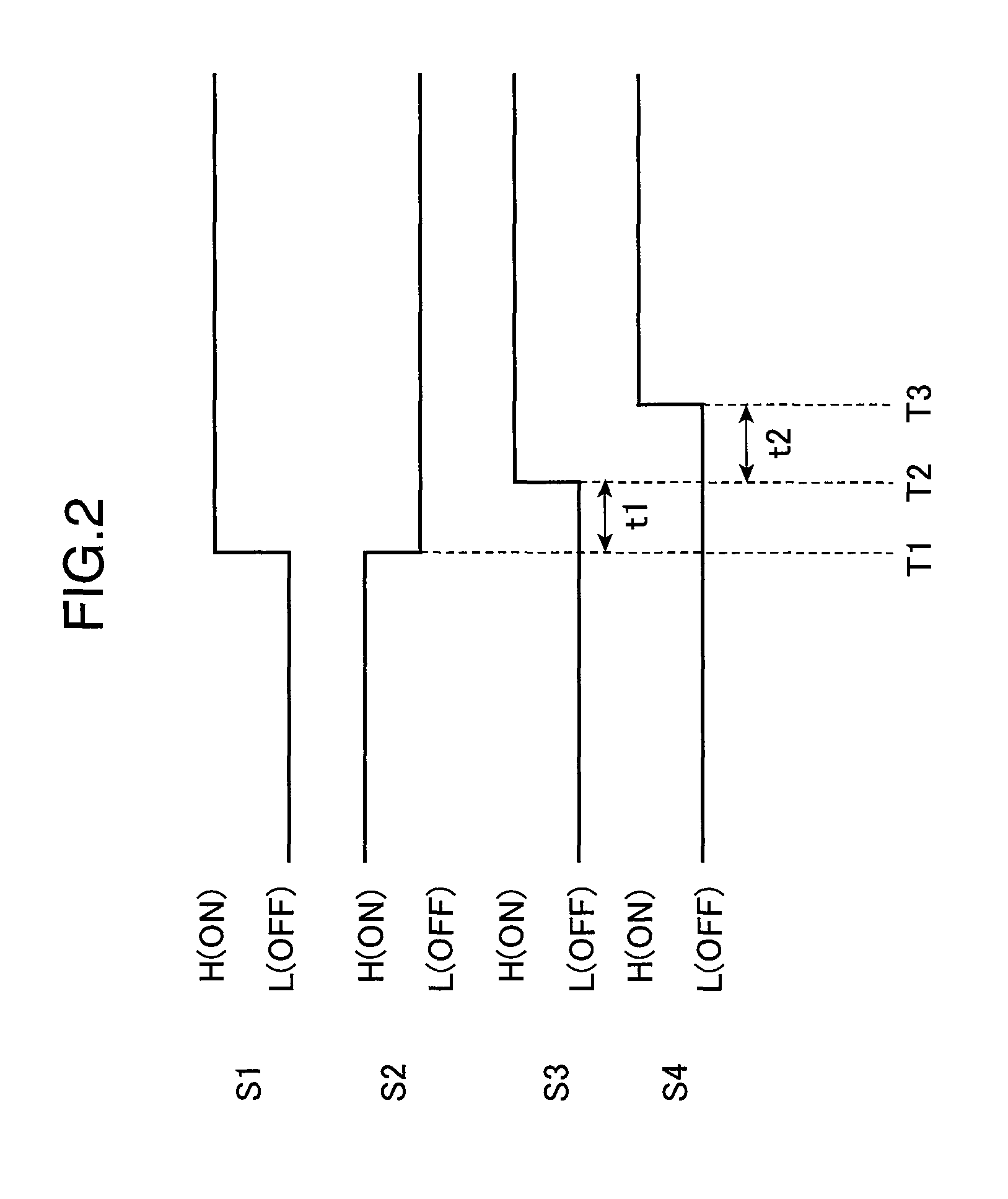
A capacitor 16 is charged by turning on a switching element 12, and when a relay 18 is operated, by turning off the switching element 12 and turning on a switching element 13, a constant-voltage power supply 11 and the capacitor 16 are series-connected, and a switching element 14 is turned on to cause the series circuit of the constant-voltage power supply 11 and the capacitor 16 to be connected to a relay coil 20, so that the voltage resulting from addition of the output voltage of the constant-voltage power supply 11 and the charging voltage of the capacitor 16 is supplied to the relay coil 20, whereby causing the relay 18 to be turned on, after which the capacitor 16 is gradually discharged by means of the relay coil 20.

Description

RELATED APPLICATIONS[0001]This application is the U.S. National Phase under 35 U.S.C. §371 of International Application No. PCT / JP2008 / 000934, filed on Apr. 10, 2008, which in turn claims the benefit of Japanese Application No. 2007-132733, filed on May 18, 2007, the disclosures of which Applications are incorporated by reference herein.TECHNICAL FIELD[0002]This invention relates to a relay driving circuit which drives a relay, and to a battery pack which uses such a circuit.BACKGROUND ART[0003]Circuits which drive relays are generally circuits which maintain a contact by applying a constant voltage to a relay coil by means of a constant-voltage power supply.[0004]However, when a relay is driven under constant voltage, the following problem is known to arise. Normally a relay contact is held closed by the magnetomotive force arising in the relay coil within the relay due to current flowing in the relay coil. This magnetomotive force is determined by the current flowing in the relay ...

Claims


Application Information

Patent Timeline
Patent Type & Authority Patents(United States)
IPC IPC(8): H02J1/00
CPCH01H47/043H01M10/44Y02E60/10H01H47/04H01H47/22
Inventor MORIMOTO, NAOHISA
Owner PANASONIC CORP
Learn More