Method and apparatus for measuring raman signals

a technology of raman signal and measurement method, which is applied in the direction of optical radiation measurement, instruments, spectrometry/spectrophotometry/monochromators, etc., can solve the problems of difficult quantitative measurement of the amount and concentration of analyte, and limited uniformity of signal intensity, so as to reduce signal strength variability and reduce signal strength. variability

Active Publication Date: 2012-07-03
FUJIFILM CORP
View PDF12 Cites 4 Cited by
  • Summary
  • Abstract
  • Description
  • Claims
  • Application Information

AI Technical Summary

Benefits of technology

[0012]The SERS technique is able to enhance weak Raman scattered light, and can thus be used to monitor Raman scattered light from an analyte at high sensitivity. However, not only Raman scattered light from the analyte, but also light such as Raman scattered light and fluorescent light from the background (i.e., areas within a detection surface other than a region where the analyte was placed) are also enhanced. As a result, the signal variance between microstructure plates becomes larger.
[0018]It is therefore an object of the present invention to provide a method of measuring Raman signals which is able to reduce signal strength variability between microstructure plates. Another object of the invention is to provide an apparatus for measuring Raman signals which similarly is able to reduce signal strength variability between microstructure plates.

Problems solved by technology

When the signals are variable in this way, it is difficult to quantitatively measure the amount and concentration of the analyte.
Unfortunately, because it is impossible to manufacture perfectly uniform microstructure plates, the uniformity of signal intensity has been limited.

Method used


Image

  • Method and apparatus for measuring raman signals
  • Method and apparatus for measuring raman signals
  • Method and apparatus for measuring raman signals

Examples


examples

[0154]The present invention is described more fully in the following example, which is illustrative and should not be construed as limiting the invention.

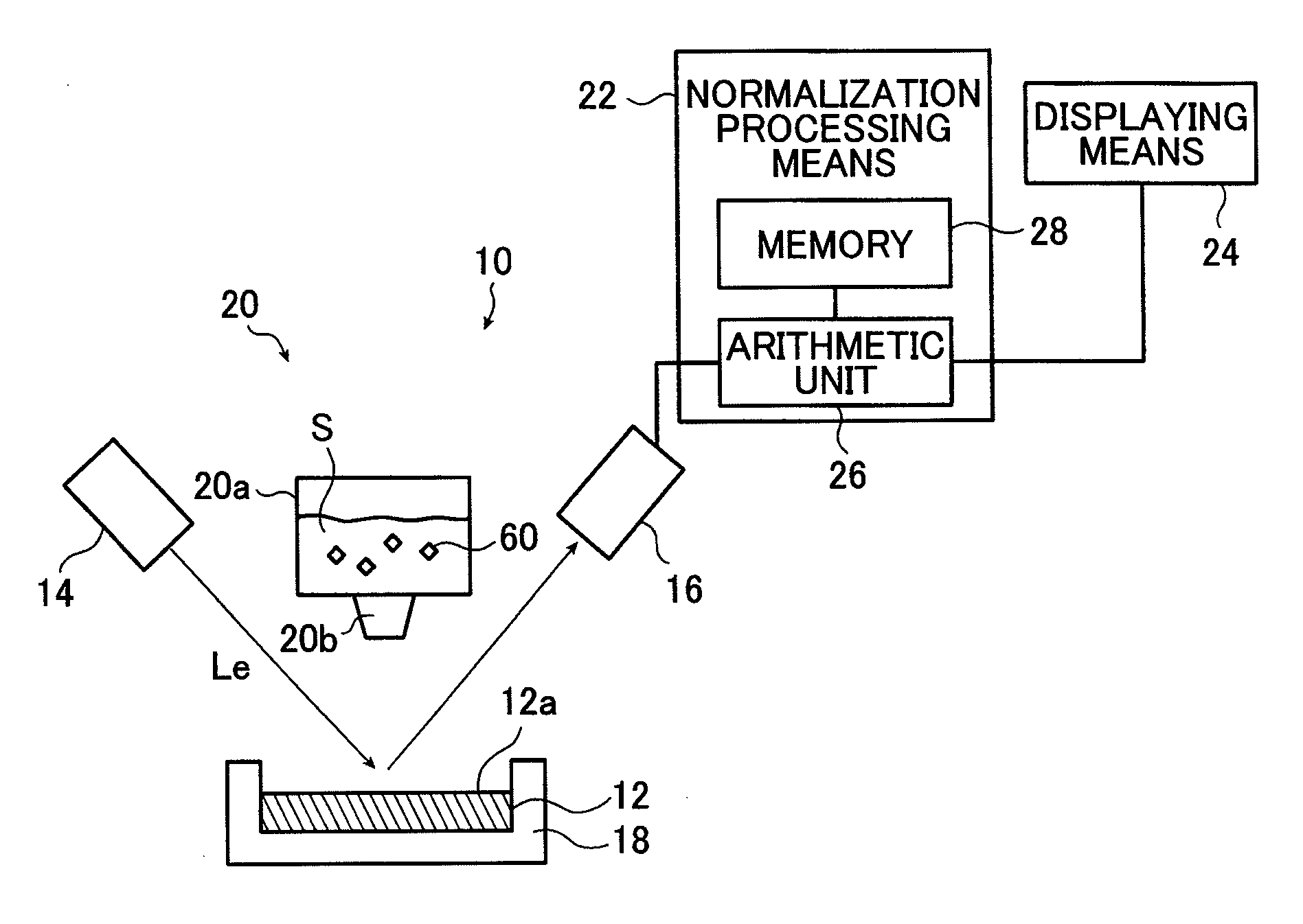
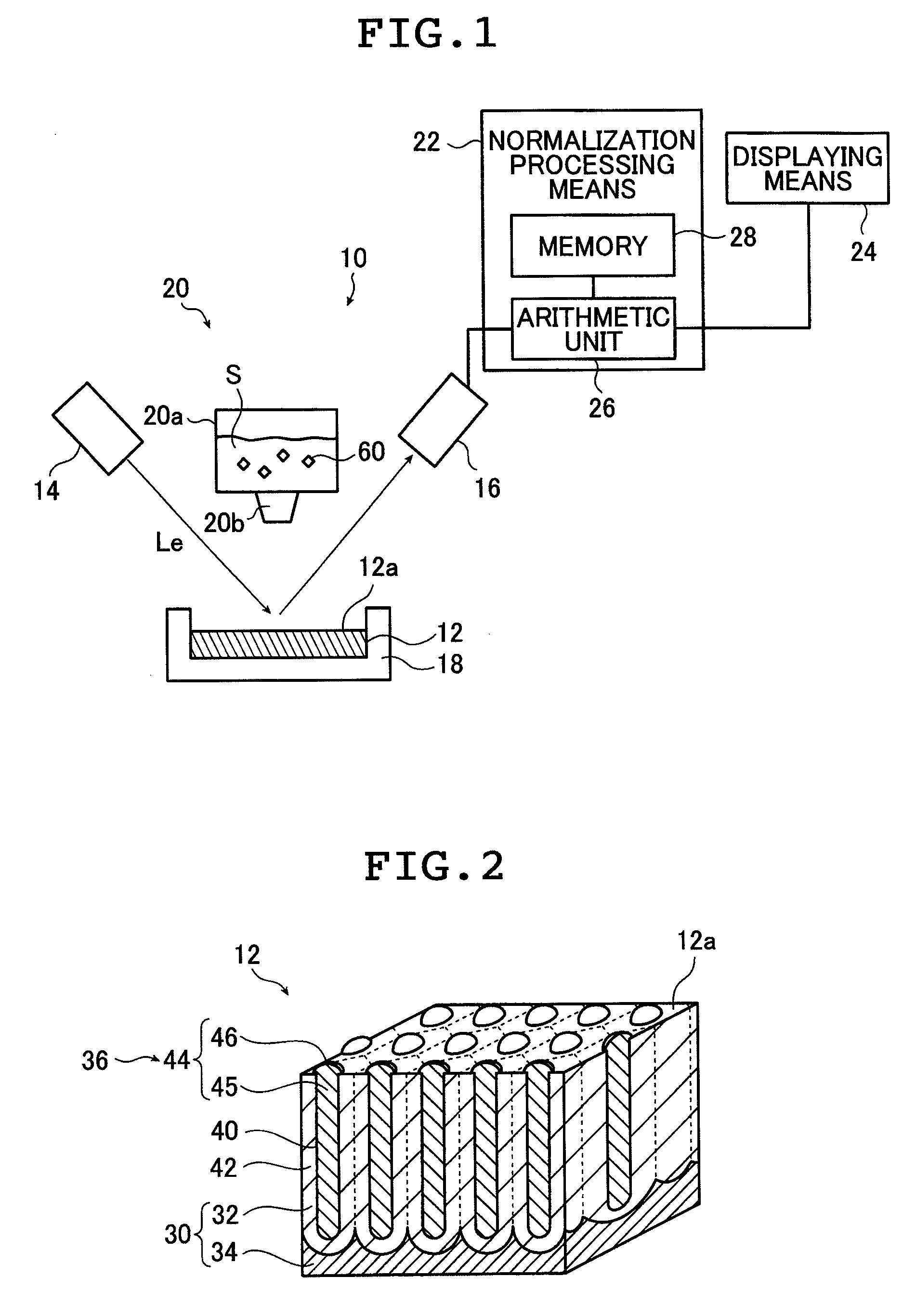
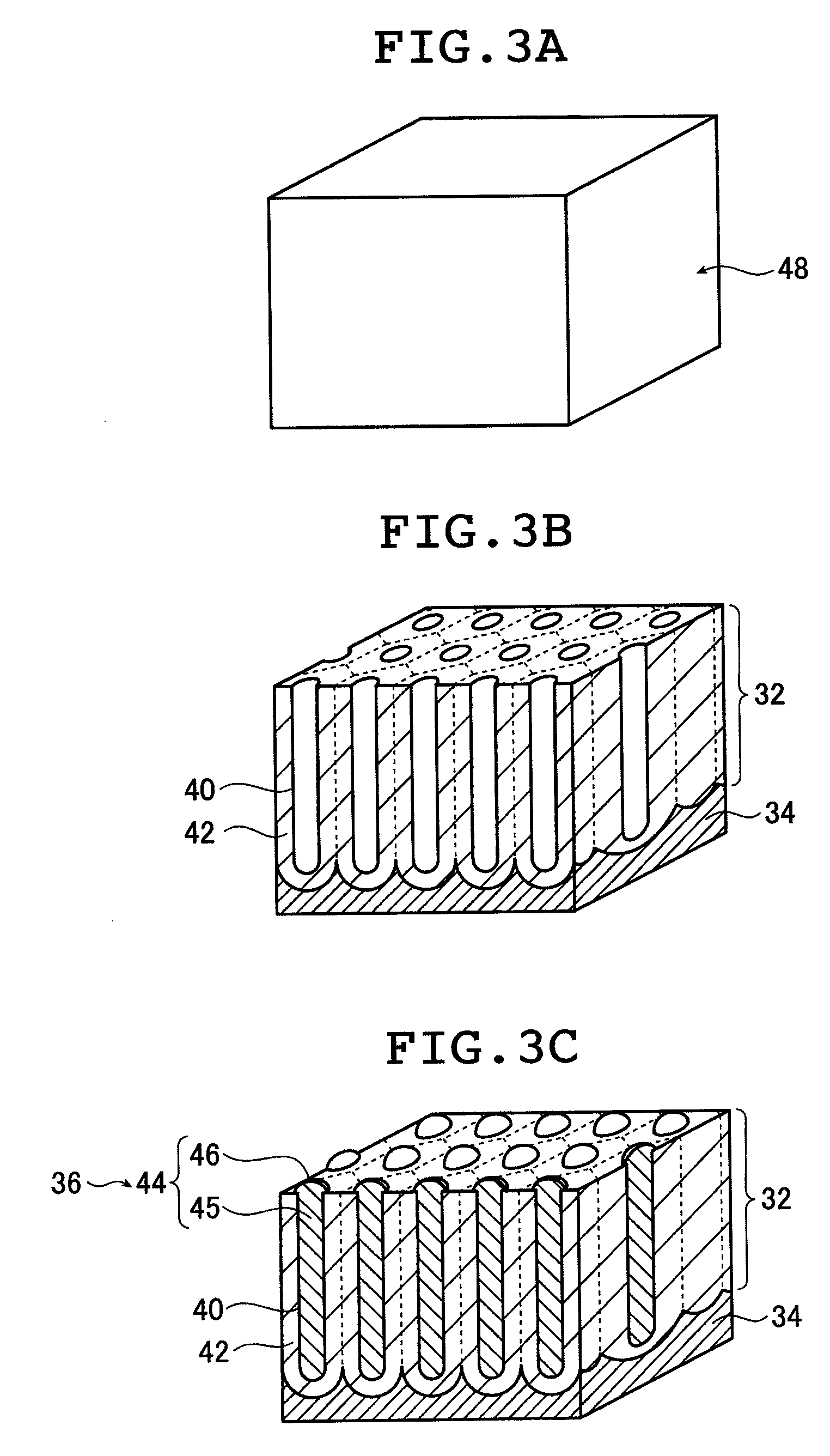
[0155]Twelve microstructure plates of the above-described construction shown in FIG. 2 were each furnished in turn as the microstructure plate 12.

[0156]Plate 1 was mounted, as the microstructure plate 12, at a given position in the Raman signal measuring apparatus 10 shown in FIG. 1, and secured in place.

[0157]Next, 100 μM of a liquid sample S was prepared by dissolving an analyte 60 (Rhodamine 6G, having a key band at 1360 cm−1) in ethanol. This liquid sample S was added dropwise onto the detection surface of Plate 1 using a dropper and dried, thereby causing the analyte 60 to adhere to the surface of the detection surface 12a.

[0158]Subsequently, the detection surface 12a was irradiated with a semiconductor laser having an output of 2 mW and an excitation wavelength of 785 nm, thereby generating an enhanced field on the detection...


PUM


Abstract

A method of measuring Raman signals comprises: an analyte placing step of placing an analyte on a detection surface of a microstructure plate which generates an enhanced electric field when irradiated with excitation light; an irradiating step of irradiating the detection surface with the excitation light so that the enhanced electric field is generated around the detection surface and light is emitted from the analyte and the detection surface to be enhanced by the generated enhanced electric field; a Raman signal obtaining step of detecting the enhanced light to obtain a Raman signal emitted from the analyte and a background signal for use as a reference, the Raman signal and the background signal having respective intensities; and a normalizing step of normalizing the Raman signal from the analyte by dividing the intensity of the Raman signal from the analyte by the intensity of the background signal obtained as the reference.

Description

[0001]The entire contents of all documents cited in this specification are incorporated herein by reference.BACKGROUND OF THE INVENTION[0002]The present invention relates to a method and apparatus for measuring Raman signals by radiating a detection surface on which an analyte has been placed with excitation light and, in a state where an enhanced electric field has been generated at the detection surface, detecting Raman scattered light from the analyte.[0003]Raman spectroscopy is a technique, used for identifying substances and other purposes, in which Raman scattered light obtained by radiating a substance with single-wavelength light is spectrally analyzed to give Raman scattered light signals. Raman spectroscopy can be used to measure (e.g., identify) biosamples.[0004]In addition, as mentioned in the method for quantitatively analyzing a substrate by Raman spectroscopy described in JP 2000-258346 A, because there is a correlation between the concentration of the substance to be...

Claims


Application Information

Patent Timeline
Patent Type & Authority Patents(United States)
IPC IPC(8): G01J3/44
CPCG01J3/0205G01J3/0264G01J3/027G01J3/44G01N21/65
Inventor NAYA, MASAYUKITOMARU, YUICHIMURAKAMI, NAOKI
Owner FUJIFILM CORP
Why Eureka
Try Eureka