Arrangement structure for canister of saddle type vehicle

a canister and canister technology, applied in the direction of combustion air/fuel air treatment, transportation items, cycle equipments, etc., can solve the problems of increasing product costs, difficult pipe layout, and long length of charge hose for introducing evaporated fuel into the canister, so as to reduce the length of charge hose and purge hose, the effect of reducing the cost of parts and improving the feasibility of pipe layou

Inactive Publication Date: 2012-07-10
HONDA MOTOR CO LTD
View PDF3 Cites 11 Cited by
  • Summary
  • Abstract
  • Description
  • Claims
  • Application Information

AI Technical Summary

Benefits of technology

[0006]Therefore, an arrangement structure is provided for a canister of a saddle type vehicle wherein a canister can be arranged closely to a fuel tank to simplify a pipe arrangement structure.
[0015]Since the canister is disposed in the dead space below the rear inclined wall formed at a rear portion of the tank lower half in relation to pressing, the canister can be disposed sufficiently closely to the fuel tank without intentionally providing a special purpose space for disposing the canister. Further, since the canister is disposed at a position close to both of the engine and the fuel tank, the length of a charge hose and a purge hose can be reduced to achieve reduction of the part cost and improvement in feasibility in layout of pipes and make the part arrangement around the fuel tank compact.
[0016]Since the purge control valve is disposed in the dead space below the rear inclined wall of the tank lower half together with the canister, the purge control valve can be disposed sufficiently closely to the canister and the engine without intentionally providing a special purpose space for disposing the purge control valve. Accordingly, the length of the purge hose which connects the canister and the purge control valve and which connects the purge control valve and the engine can be reduced to achieve reduction of the part cost and improvement in feasibility in layout of pipes and make the part arrangement around the fuel tank compact.
[0017]The canister is disposed nearer to the rear inclined wall than the line extended in the die cutting direction of the tank lower half from the crossing point between the rear inclined wall of the tank lower half and the joining flange in the die cutting direction of the tank lower half. Therefore, the canister can be disposed more compactly effectively utilizing the dead space provided by the draft angle of the tank lower half.
[0019]Since the swing unit including the engine is supported for upward and downward rocking motion at a position close to the canister and the purge control valve, the range of the rocking motion of the purge hose can be reduced.

Problems solved by technology

However, in this conventional arrangement structure for a canister, since the canister for collecting evaporated fuel in the fuel tank is arranged below a rear end portion of the seat, the length of a charge hose for introducing evaporated fuel in the fuel tank into the canister becomes long, and the product cost increases as much and layout of pipes becomes difficult.

Method used


Image

  • Arrangement structure for canister of saddle type vehicle
  • Arrangement structure for canister of saddle type vehicle
  • Arrangement structure for canister of saddle type vehicle

Examples


Embodiment Construction

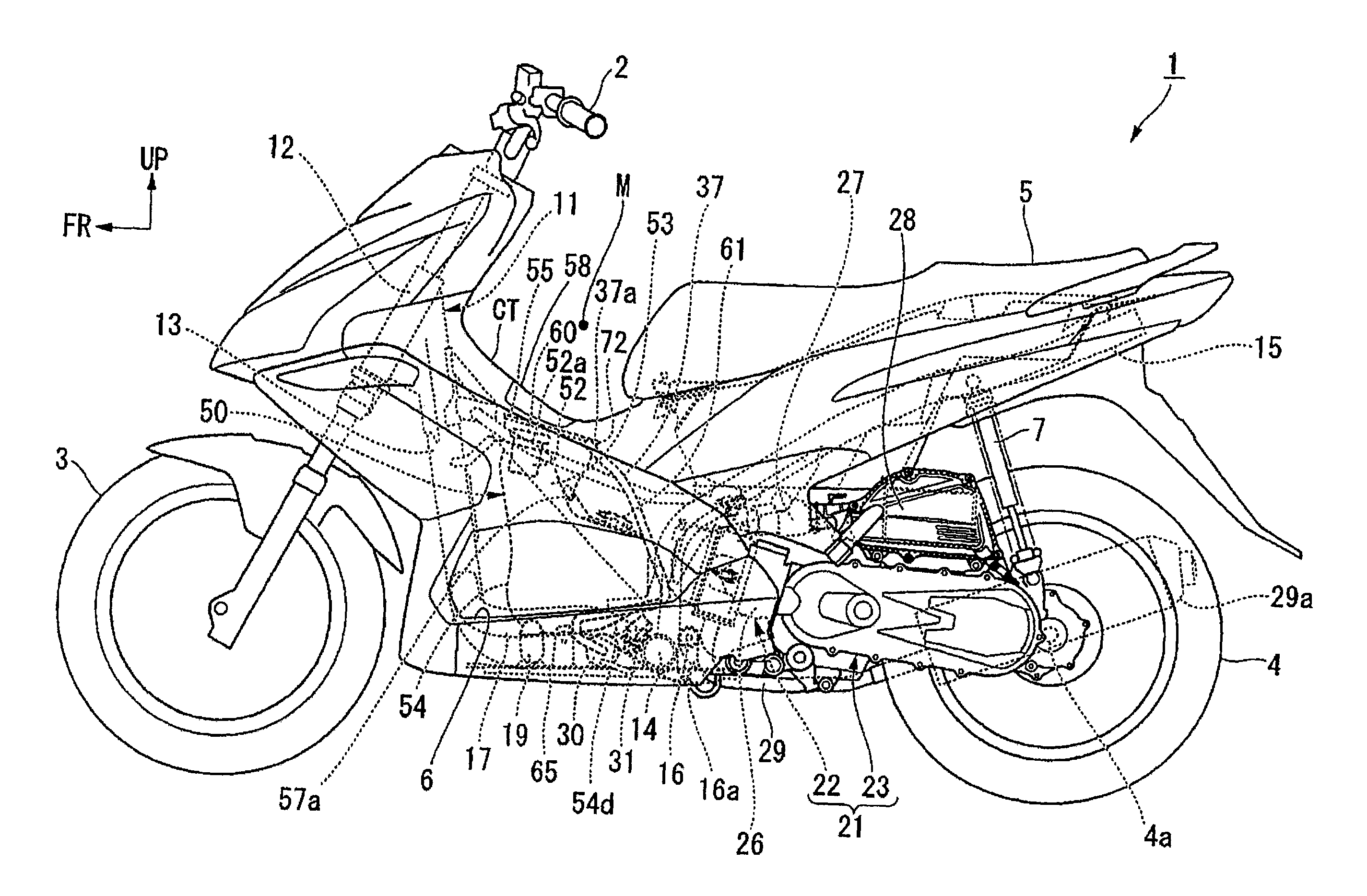
[0026]In the following, an embodiment of the present invention is described with reference to the drawings. It is to be noted that, unless otherwise specified, the directions such as the forward, rearward, leftward and rightward directions in the following description coincide with the directions with reference to the vehicle. Further, in the figures, an arrow mark FR denotes the vehicle forward direction and another arrow mark UP denotes the vehicle upward direction.

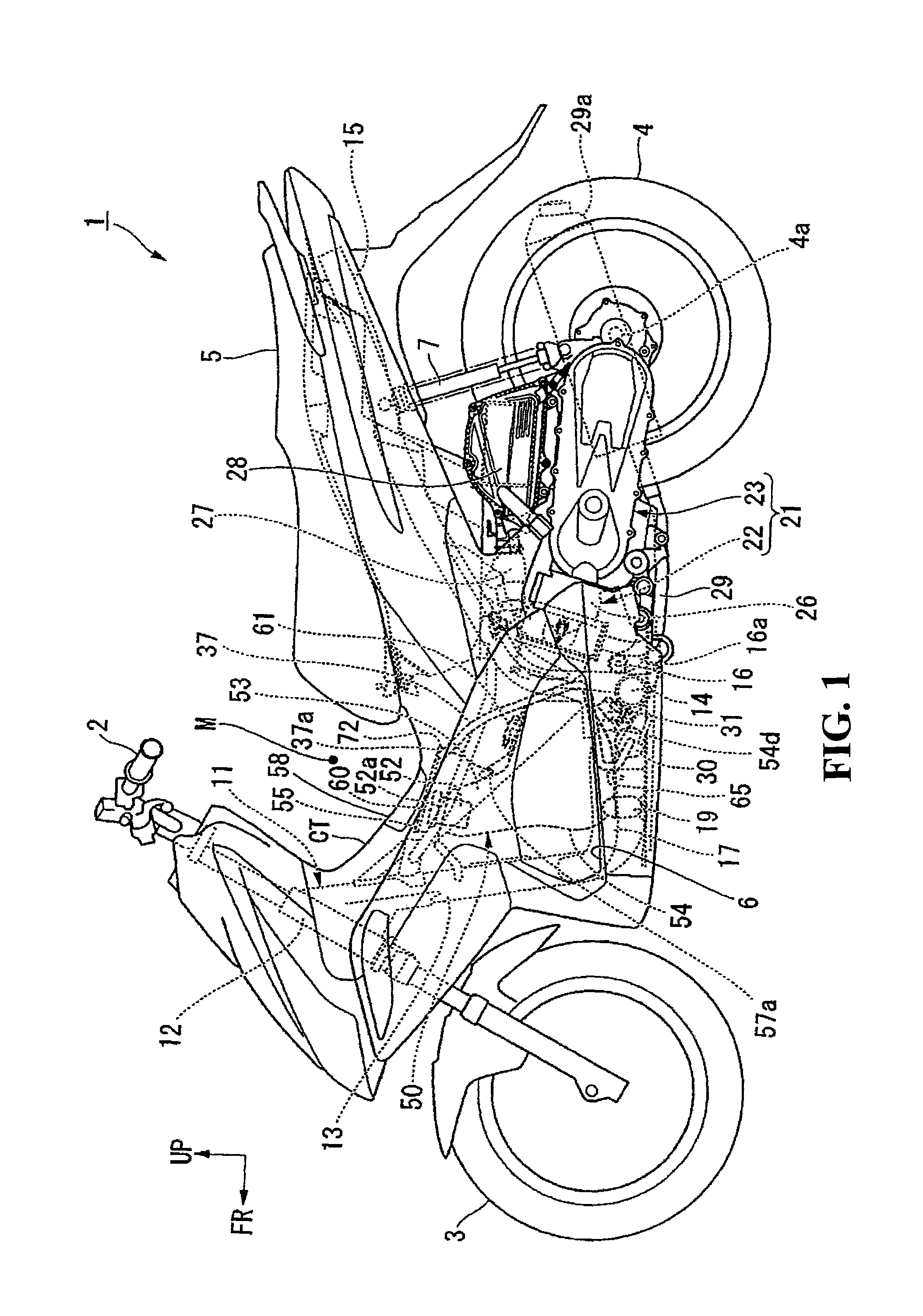
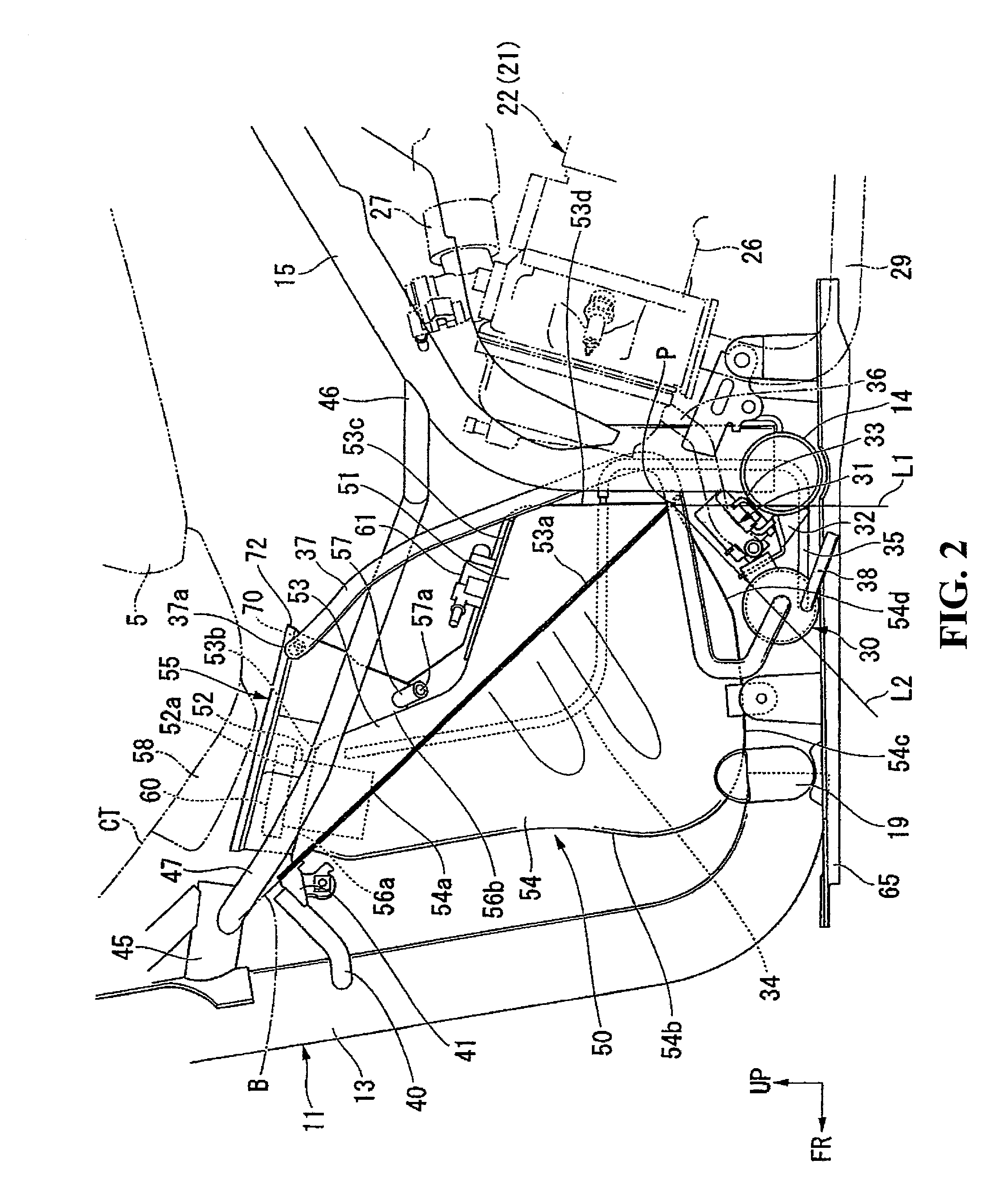
[0027]FIG. 1 is a view showing a side face of a motorcycle 1 of the scooter type (scooter type vehicle) which is a form of saddle type vehicle.

[0028]As shown in FIG. 1, this motorcycle 1 includes a front wheel 3 steered by a handle bar 2 and a rear wheel 4 driven by a swing unit (power unit) 21.

[0029]Steering system parts including the handle bar 2 and the front wheel 3 are supported for steering movement on a head pipe 12 at a front end of a vehicle body frame 11. The swing unit 21 is supported at a front end portion t...


PUM


Abstract

An arrangement structure is provided for a canister of a saddle type vehicle wherein a canister can be arranged closely to a fuel tank to simplify a pipe arrangement structure. A fuel tank disposed forward of an engine is structured such that a tank upper half and a tank lower half of a concave shape formed by pressing are joined together at joining flanges. The joining flanges are disposed on a vehicle body such that a front portion thereof is positioned on the upper side. A rear inclined wall, which is inclined toward a rear upper direction such that it forms a substantially right angle to the joining flange, is provided at a rear portion of the tank lower half. A canister is disposed in a dead space below the rear inclined wall.

Description

TECHNICAL FIELD[0001]An arrangement structure is provided for a canister which is incorporated in a saddle type vehicle such as a motorcycle and collects fuel gas evaporated in a fuel tank.BACKGROUND OF THE INVENTION[0002]In a saddle type vehicle such as a motorcycle, a canister for collecting evaporated fuel in a fuel tank is provided, and the fuel collected by the canister is used for combustion in an engine.[0003]As a canister arrangement structure for a scooter type vehicle, a canister arrangement structure is known wherein a canister is arranged in a dead space downward of a rear end portion of a seat for a passenger (refer to Japanese Patent Laid-Open No. Hei 4-353257).[0004]In the scooter type vehicle disclosed in Japanese Patent Laid-Open No. Hei 4-353257, a power unit wherein an engine and a power transmitting apparatus are integrated with each other is provided for upward and downward rocking motion below the seat, and a fuel tank for reserving fuel is provided forward of ...

Claims


Application Information

Patent Timeline
Patent Type & Authority Patents(United States)
IPC IPC(8): B60K15/073
CPCB62J37/00F02M37/0076F02M25/0854F02B61/02F02M37/007
Inventor HOSOYA, YUKIOMORIKAWA, YUICHIRO
Owner HONDA MOTOR CO LTD
Why Eureka
Try Eureka