Spinal interbody system and method

a technology of interbody and spine, applied in the field of spine implants, can solve the problems of reducing life quality, reducing mobility, and severe pain, and achieve the effects of reducing or eliminating the need to bend the plate, and reducing or limiting the impa

Active Publication Date: 2012-07-10
ZIMMER BIOMET SPINE INC
View PDF28 Cites 213 Cited by
  • Summary
  • Abstract
  • Description
  • Claims
  • Application Information

AI Technical Summary

Benefits of technology

[0011]Embodiments of the present invention provide advantages over prior art spinal implant systems and methods by prevent the expulsion of an interbody device.
[0012]Embodiments of the present invention can provide an advantage over prior art spinal implant systems and methods by limiting reducing or limiting the impacts between the interbody device and the plate.
[0013]Embodiments of the present invention provide another advantage over prior art spinal implant systems and methods by allowing a stabilization plate to be rotated relative to an interbody after the interbody is in place. This allows for better positioning of the plate and reduces or eliminates the need to bend the plate to conform it to the spine.
[0014]Embodiments of the present invention provide another advantage by allowing a user to select the depth of insertion of an interbody device relative to a plate. This helps ensure, for example, that the interbody device can be placed near the anterior side of the vertebrae, which is often preferred by surgeons.

Problems solved by technology

A number of maladies afflict the spine, causing severe pain, loss of mobility and decreased quality of life.
Additionally, vertebral fractures and other trauma can cause spinal suffering.
Unfortunately, this requires that the surgeon open the patient on both the anterior and posterior sides.
One problem with this technique is that movement of the interbody device can assert impact forces on the plate causing the bone screws attaching the plate to the spine to back out.

Method used


Image

  • Spinal interbody system and method
  • Spinal interbody system and method
  • Spinal interbody system and method

Examples


Embodiment Construction

[0035]Preferred embodiments of the invention are illustrated in the FIGURES, like numerals being used to refer to like and corresponding parts of the various drawings.

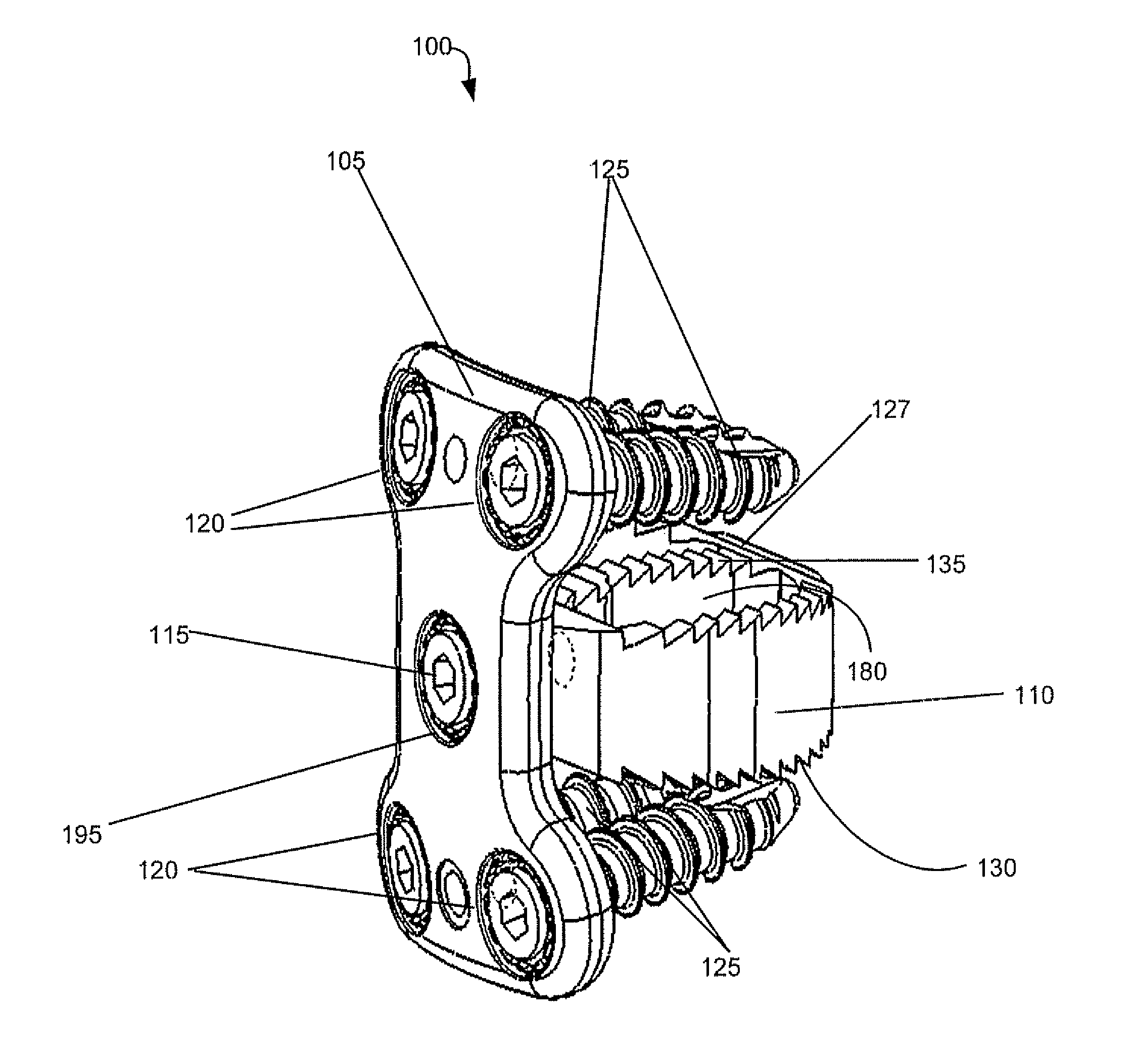
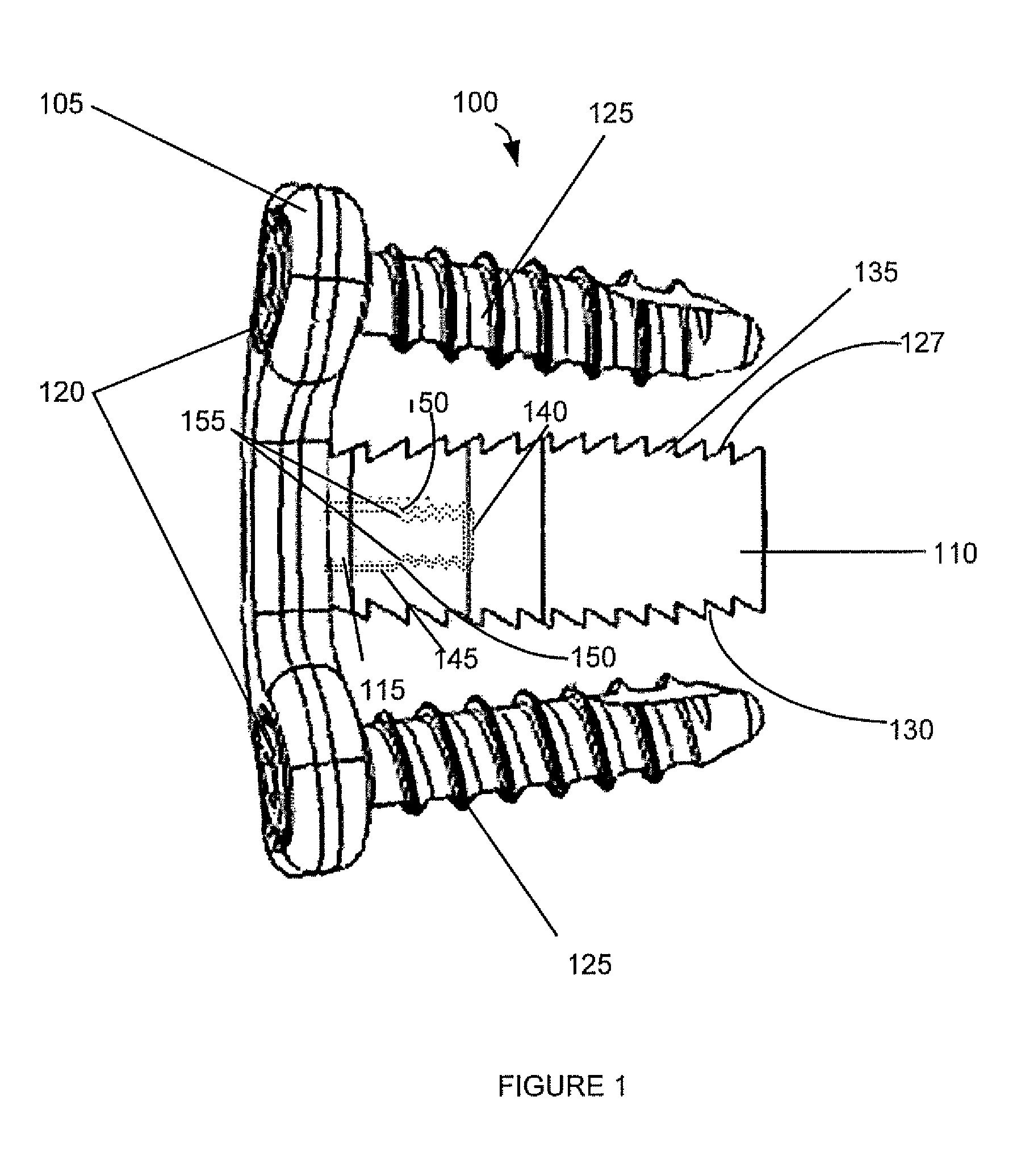
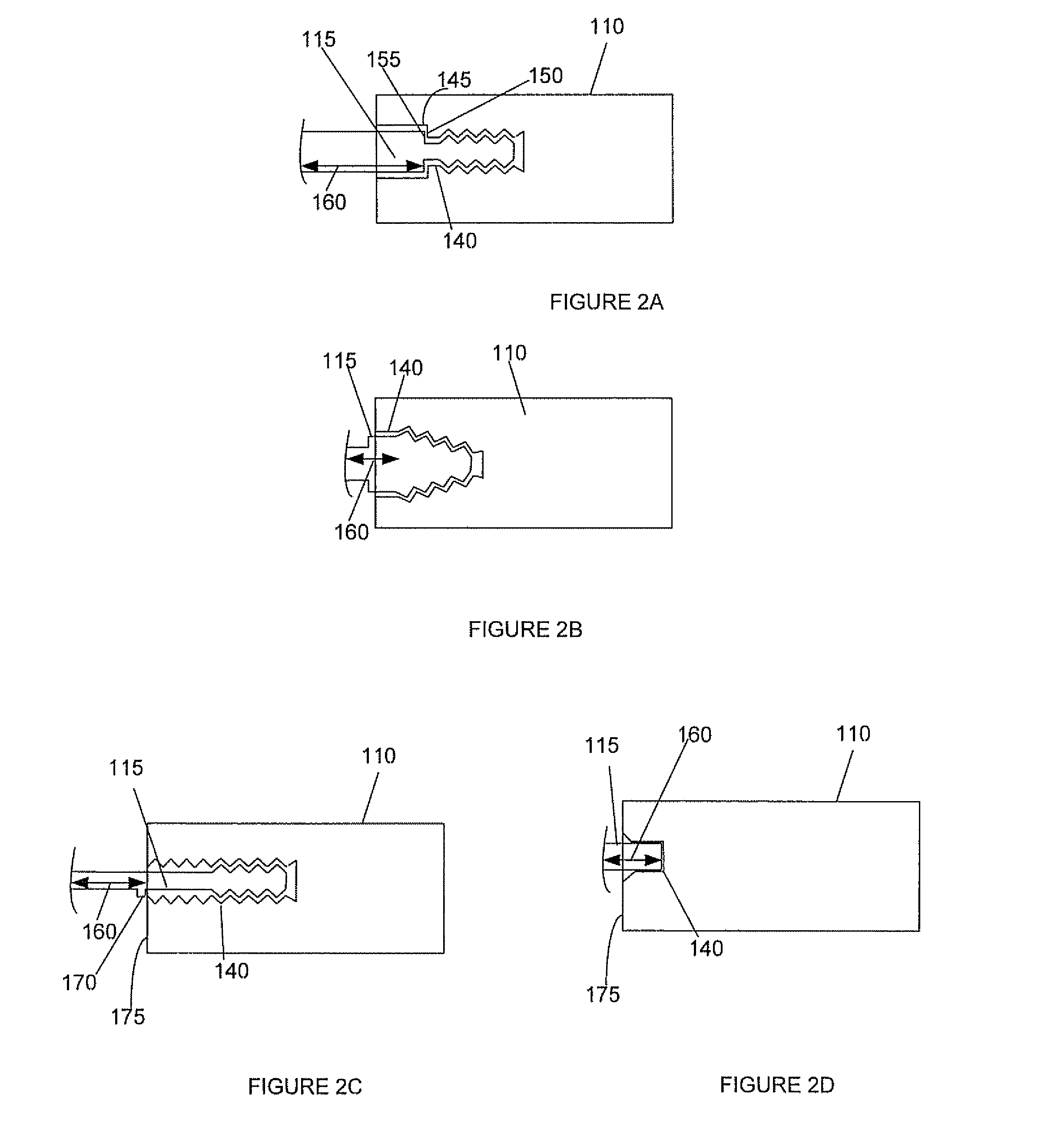
[0036]Embodiments of the present invention provide systems and methods for spinal stabilization. In general, a plate attached to one or more vertebrae can prevent expulsion of an interbody device from a disc space. The plate and interbody device can be coupled by an attachment member. According to one embodiment, the attachment member is coupled to the plate and includes a portion inserted in a threaded or non-threaded cavity of the interbody. Preferably, the coupling between the plate and attachment member allows rotation in three dimensions thereby allowing the plate to rotate relative to the interbody. This allows the plate to be better positioned for attachment to the spine during an operation. Additionally, the attachment member and interbody can be shaped so that the interbody is a specified distance away from th...


PUM

PropertyMeasurementUnit
distanceaaaaaaaaaa
angleaaaaaaaaaa
angleaaaaaaaaaa

Abstract

Embodiments of the present invention provide spinal implant systems and methods. According to one embodiment, a plate attached to one or more vertebrae can prevent expulsion of an interbody device from a disc space. The plate and interbody device can be coupled by an attachment member. According to one embodiment, the attachment member is coupled to the plate and includes a portion inserted in a threaded or non-threaded cavity. Preferably, the coupling between the plate and attachment member allows rotation in three dimensions thereby allowing the plate to rotate relative to the interbody device. This allows the plate to be better positioned for attachment to the spine during an operation.

Description

TECHNICAL FIELD OF THE INVENTION[0001]Embodiments of the present invention relate to spinal implants. Even more particularly, embodiments of the present invention relate to interbody devices implanted between vertebrae.BACKGROUND OF THE INVENTION[0002]A number of maladies afflict the spine, causing severe pain, loss of mobility and decreased quality of life. Some examples of such disorders include degenerative disc disease, scoliosis, spinal deformities and other spinal conditions. Additionally, vertebral fractures and other trauma can cause spinal suffering.[0003]Some conditions can be treated by surgical techniques such as spinal fusion. In spinal fusion, vertebrae are fused together by bone growth to immobilize the vertebrae and reduce pain. In spinal fusion procedures, a small interbody device of plastic, titanium or other biocompatible material is inserted between the vertebrae in place of the natural intervertebral disc. Often a surgeon will perform an anterior procedure to in...

Claims


Application Information

Patent Timeline
Patent Type & Authority Patents(United States)
IPC IPC(8): A61F2/44
CPCA61B17/7059A61F2/4455A61B17/8047A61B17/8052A61B17/8057A61F2002/2835A61F2002/30166A61F2002/30172A61F2002/30179A61F2002/30331A61F2002/30408A61F2002/30428A61F2002/30433A61F2002/30471A61F2002/30553A61F2002/30578A61F2002/30604A61F2002/30616A61F2002/30649A61F2002/30713A61F2002/30777A61F2002/30795A61F2002/30797A61F2002/30904A61F2002/30924A61F2002/30925A61F2220/0025A61F2220/0033A61F2220/0041A61F2220/0091A61F2230/0028A61F2230/0052A61F2230/0058A61F2250/0008A61F2250/0087A61F2310/00407A61F2310/00796A61F2310/00976A61F2002/3071A61F2002/30922
Inventor GRAY, WAYNE
Owner ZIMMER BIOMET SPINE INC
Why Eureka
Try Eureka