Rotor of permanent magnet rotary machine and manufacturing method of rotor

a technology of rotary machine and rotor, which is applied in the direction of magnetic circuit rotating parts, instruments, magnetic circuit shape/form/construction, etc., can solve the problems of unsuitability of rotary machine employing ipm rotor, significant leakage of magnetic flux within the rotor, and distortion of surface flux distribution, so as to facilitate the detection of the angular position of the rotor, improve the saliency of the rotor, and avoid the effect of increasing noise or vibration

Inactive Publication Date: 2012-07-10
MITSUBISHI ELECTRIC CORP
View PDF48 Cites 12 Cited by
  • Summary
  • Abstract
  • Description
  • Claims
  • Application Information

AI Technical Summary

Benefits of technology

[0011]The present invention is intended to overcome the aforementioned problems of the prior art. Accordingly, it is an object of the invention to provide a rotor of a permanent magnet rotary machine which can provide improved saliency of the rotor without increasing noise or vibration produced thereby, yet facilitating detection of the angular position of the rotor.
[0014]In the aforementioned rotor of the rotary machine of the invention, the conducting circuit is arranged to surround at least one permanent magnet on which the magnetic material piece is arranged. The rotor thus structured can provide increased saliency. This structure of the invention makes it possible to provide a permanent magnet rotary machine capable of operating with low noise and vibration, in which the angular position of the rotor can be detected with high accuracy even when the value of high-frequency current applied to the rotary machine is small.

Problems solved by technology

The IPM rotor, however, has such problems as substantial leakage of magnetic flux within the rotor and distortion of surface flux distribution.
Thus, the rotary machine employing the IPM rotor has been regarded as unsuitable for use in such a product that is required to operate with low noise and vibration, yet producing a high torque.
It is however difficult to produce sufficiently large variations in impedances in the conventional rotary machine that are needed for detecting the angular position of the rotor.
This approach however poses a problem that application of the high-frequency voltage of an increased amplitude would result in an increase in operating noise and vibration of the rotary machine.
The cylindrical member thus structured may cause low-order cogging torque components to occur if the cylindrical member is made of a magnetic material, for instance, or the cylindrical member thus structured may make management of dimensions of the rotor difficult due to nonuniform mechanical gaps.

Method used


Image

  • Rotor of permanent magnet rotary machine and manufacturing method of rotor
  • Rotor of permanent magnet rotary machine and manufacturing method of rotor
  • Rotor of permanent magnet rotary machine and manufacturing method of rotor

Examples


first embodiment

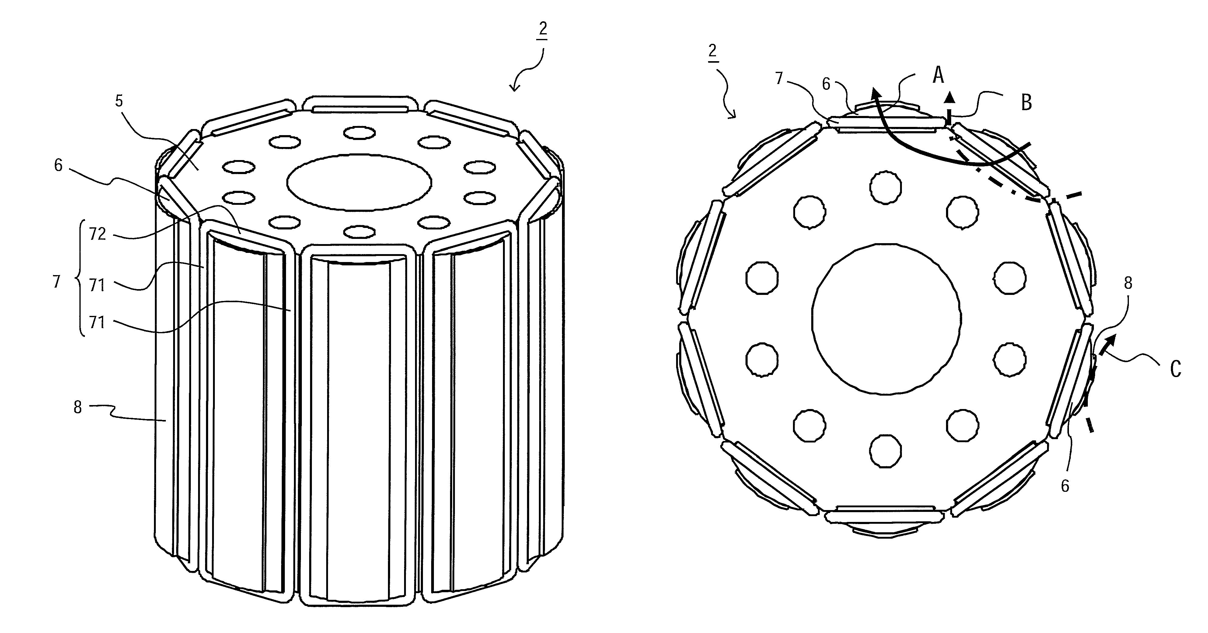
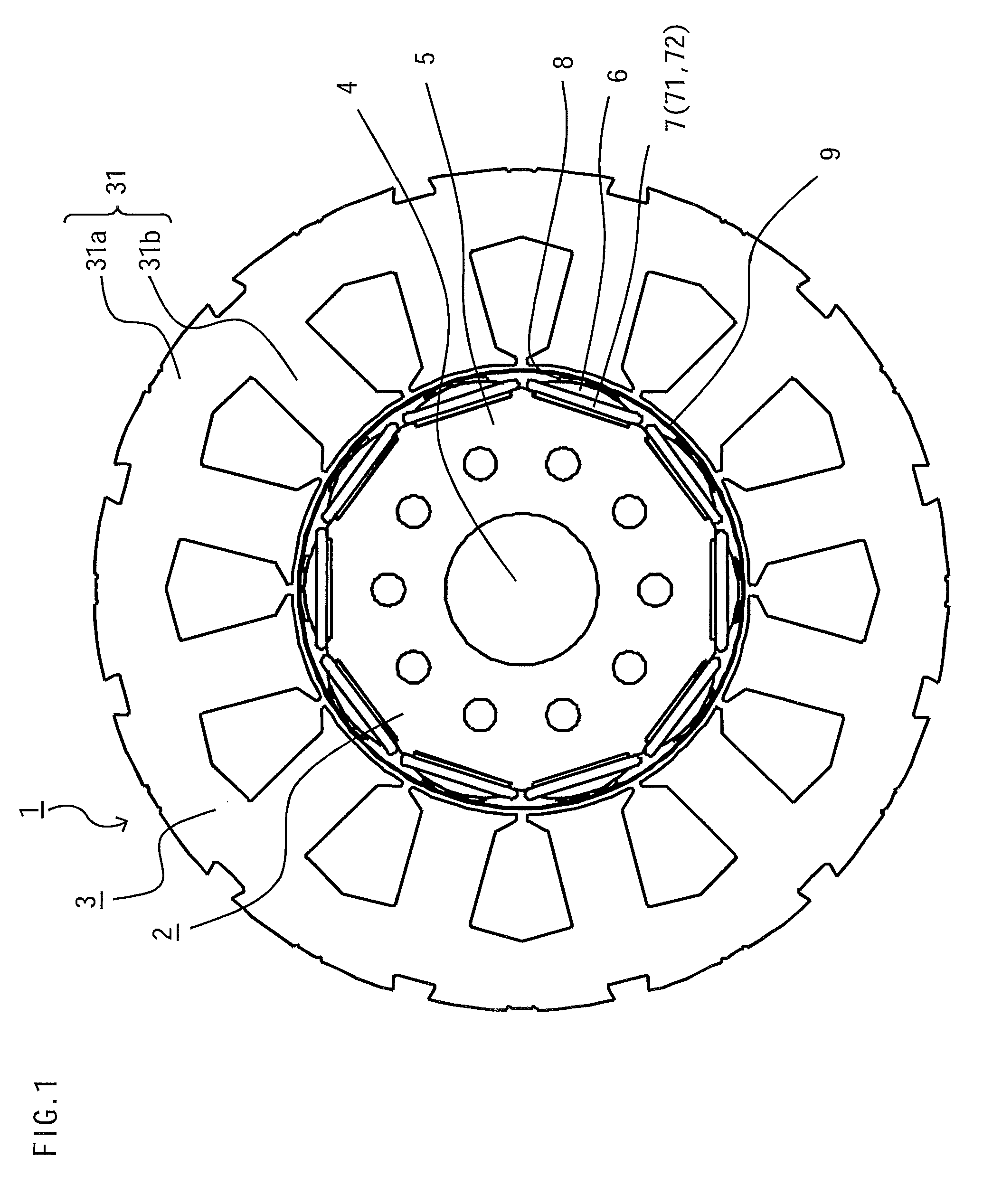
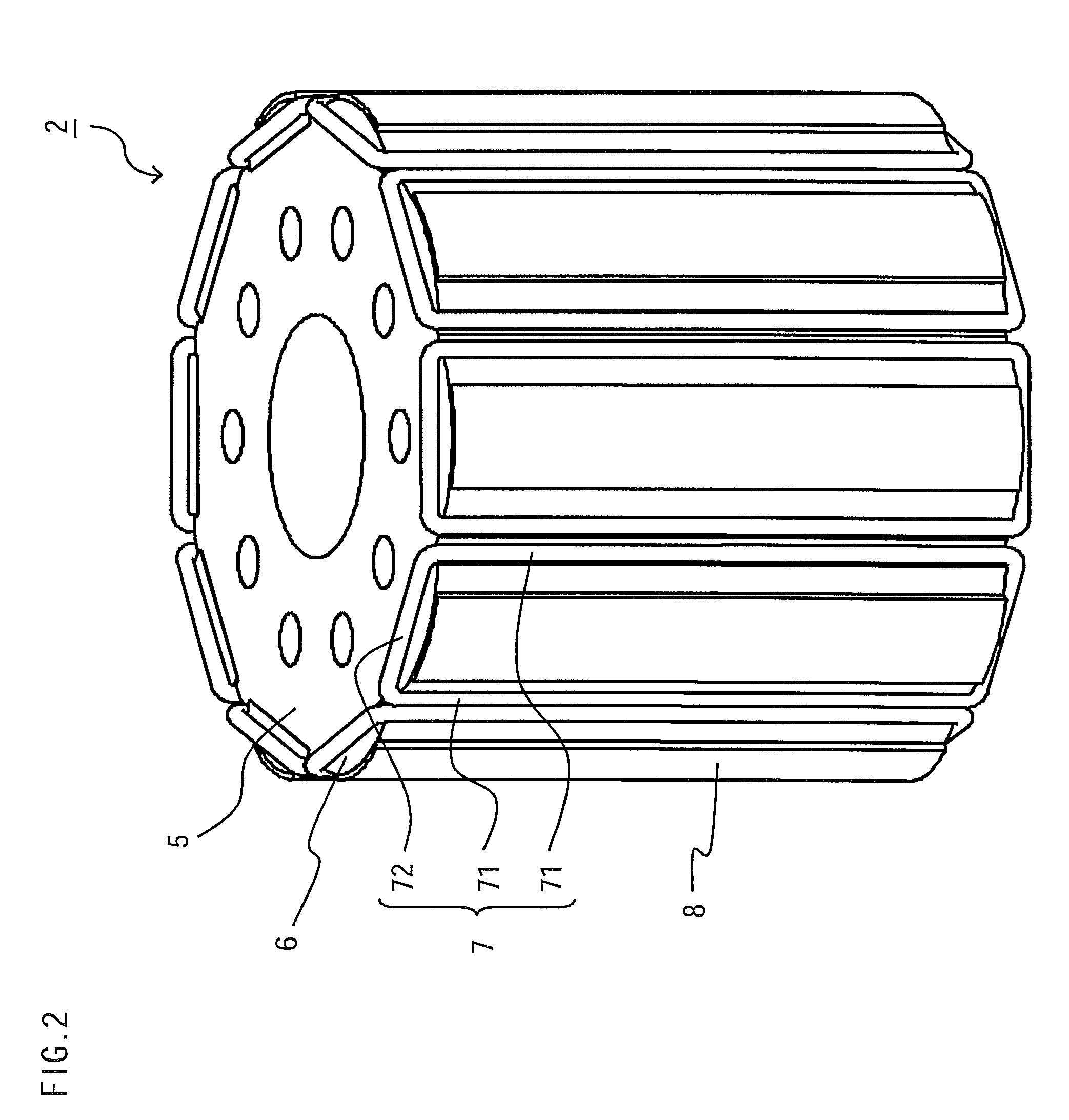
[0027]FIG. 1 is a plan view showing the structure of a permanent magnet rotary machine (hereinafter referred to simply as the rotary machine) 1 according to a first embodiment of the invention, and FIG. 2 is a perspective view of a rotor 2 of the rotary machine 1.

[0028]As shown in FIGS. 1 and 2, the rotary machine 1 includes the rotor 2 and a stator 3 arranged to surround a circumferential surface of the rotor 2. The rotor 2 and the stator 3 are disposed with a specific air gap therebetween. Although not illustrated in detail, the stator 3 includes a stator core 31 having a yoke 31a and teeth 31b and stator coils 32 (not shown) wound around the individual teeth 31b.

[0029]The rotor 2 includes a rotary shaft 4, a rotor core 5 fixed around a circumferential surface of the rotary shaft 4, a plurality of permanent magnets 6 arranged on a circumferential surface of the rotor core 5 at specific intervals along a circumferential direction thereof, a plurality of conducting circuits 7 arran...

second embodiment

[0045]While the rotor 2 of the rotary machine 1 of the foregoing first embodiment is structured such that the conducting circuits 7 provided independently of one another are arranged to surround the individual permanent magnets 6, a rotary machine according to a second embodiment of the invention described hereunder has a conducting circuit 11 which is configured differently as compared to the first embodiment. It is to be noted that elements identical or similar to those of the first embodiment are designated by the same reference numerals in the following discussion and accompanying drawings and a description of such elements is not given below.

[0046]FIG. 4 is a perspective view showing the structure of a rotor 10 according to a second embodiment. To facilitate understanding of the structure of the rotor 10, the rotary shaft 4 and the binding member 9 are not shown in FIG. 4.

[0047]Referring to FIG. 4, the conducting circuit 11 of the rotor 10 is configured with a plurality of firs...

third embodiment

[0063]While the rotor 2 of the rotary machine 1 of the foregoing first embodiment is structured such that the magnetic material pieces 8 are arranged on the outer surfaces of the individual permanent magnets 6 independently of one another, a rotor 20 of a rotary machine according to a third embodiment described below has a magnetic material piece 21 configured differently from the first embodiment. It is to be noted that elements identical or similar to those of the first embodiment are designated by the same reference numerals in the following discussion and accompanying drawings and a description of such elements is not given below.

[0064]FIG. 8 is a plan view showing the structure of the rotor 20 according to the third embodiment of the invention. As shown in FIG. 8, the magnetic material piece 21 of the rotor 20 of this embodiment is a generally cylindrical body of magnetic material including magnetic pole portions 22 and intra-pole portions 23. The magnetic pole portions 22 are ...


PUM

PropertyMeasurementUnit
electrical angleaaaaaaaaaa
thicknessaaaaaaaaaa
thicknessaaaaaaaaaa

Abstract

A rotor of a rotary machine includes a rotary shaft, a rotor core fixed to a circumferential surface of the rotary shaft, a plurality of permanent magnets arranged on a circumferential surface of the rotor core at specific intervals along a circumferential direction thereof, conducting circuits arranged to surround the permanent magnets, and magnetic material pieces arranged on outer surfaces of the individual permanent magnets. Each of the conducting circuits includes a pair of first conductor sections arranged between magnetic poles formed by the adjacent permanent magnets and a pair of second conductor sections electrically connecting the first conductor sections.

Description

BACKGROUND OF THE INVENTION[0001]1. Field of the Invention[0002]The present invention relates to a structure of a rotor of a permanent magnet rotary machine in which the rotor rotates without using commutators as well as to a method of manufacturing such a rotor.[0003]2. Description of the Background Art[0004]Japanese Patent Application Publication No. 1997-56193 describes a rotor configured with permanent magnets used in a conventional sensorless, brushless DC motor. According to the Publication, the rotor has nonmagnetic layers made of an electrically conductive nonmagnetic material formed on a circumferential surface in an angular region (e.g., 80 to 100 degrees in terms of electrical angle) from a boundary between one north pole and an adjacent south pole of the rotor in a forward running direction and in a similar angular region from the boundary of the two poles in a reverse running direction opposite to the forward running direction.[0005]Japanese Patent Application Publicati...

Claims


Application Information

Patent Timeline
Patent Type & Authority Patents(United States)
IPC IPC(8): H02K1/27H02K21/12H02K15/03
CPCG01D5/2046H02K1/223H02K29/12H02K1/278Y10T29/49012
Inventor KAWASAKI, SACHIKOAKITA, HIROYUKINAKANO, MASATSUGUMORITA, YUSUKE
Owner MITSUBISHI ELECTRIC CORP
Why Eureka
Try Eureka