Method and apparatus for measuring thermal conductivity of small, highly insulating specimens

a high-insulating, specimen technology, applied in the direction of material heat development, material thermal analysis, instruments, etc., can solve the problems of increasing the complexity of the technique of precisely measuring steady-state thermal conductivity, and reducing the convective heat transfer. , the effect of reducing radiation heat loss

Inactive Publication Date: 2012-07-17
NAT AERONAUTICS & SPACE ADMINISTATION UNITED STATES GOVERNMENT AS REPRESENTED BY THE ADMINISTATOR OF THE
View PDF16 Cites 26 Cited by
  • Summary
  • Abstract
  • Description
  • Claims
  • Application Information

AI Technical Summary

Benefits of technology

[0051]It is a further object of the invention to use a specimen thickness of 0.002 m to lower convective heat transfer by a factor of about 13 or decreasing to 0.003 m thickness wou...

Problems solved by technology

Therefore, test samples may only be available in sizes too small for the methods normally used to directly measure thermal conductivity.
In practice, this assumption is seldom valid, particularly for very low conductivity specimens surrounded by insulation of comparable thermal conductivity.
Techniques for precisely measuring steady-state thermal conductivity are much more complex than they may initially appear.
However, all the power coming from the heater does not automatically go into the sample, and the sample does not necessarily experience one-dimensional heat flow with parallel heat flux vectors through it.
Even with considerable care, this “guarded hot plate” approach is still imperfect and requires theoretical, and often experimental, c...

Method used


Image

  • Method and apparatus for measuring thermal conductivity of small, highly insulating specimens
  • Method and apparatus for measuring thermal conductivity of small, highly insulating specimens
  • Method and apparatus for measuring thermal conductivity of small, highly insulating specimens

Examples


Embodiment Construction

[0073]NASA technical memorandum NASA / TM-2009-215460, published June 2009, entitled Method for Measuring Thermal Conductivity of Small Samples Having Very Low Thermal Conductivity, by Robert A. Miller and Maria A. Kuczmarksi, Glenn Research Center, Cleveland, Ohio is incorporated herein by reference hereto.

Apparatus Design

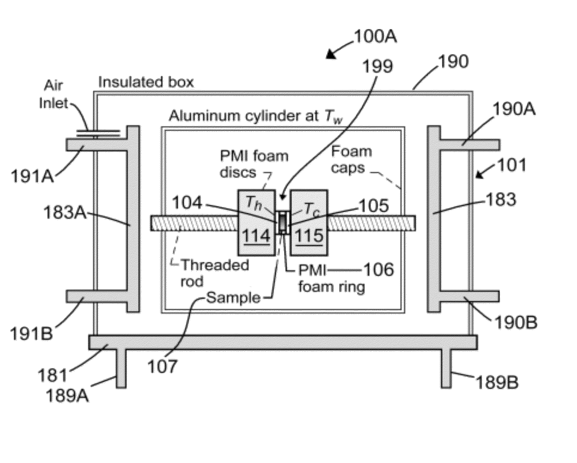
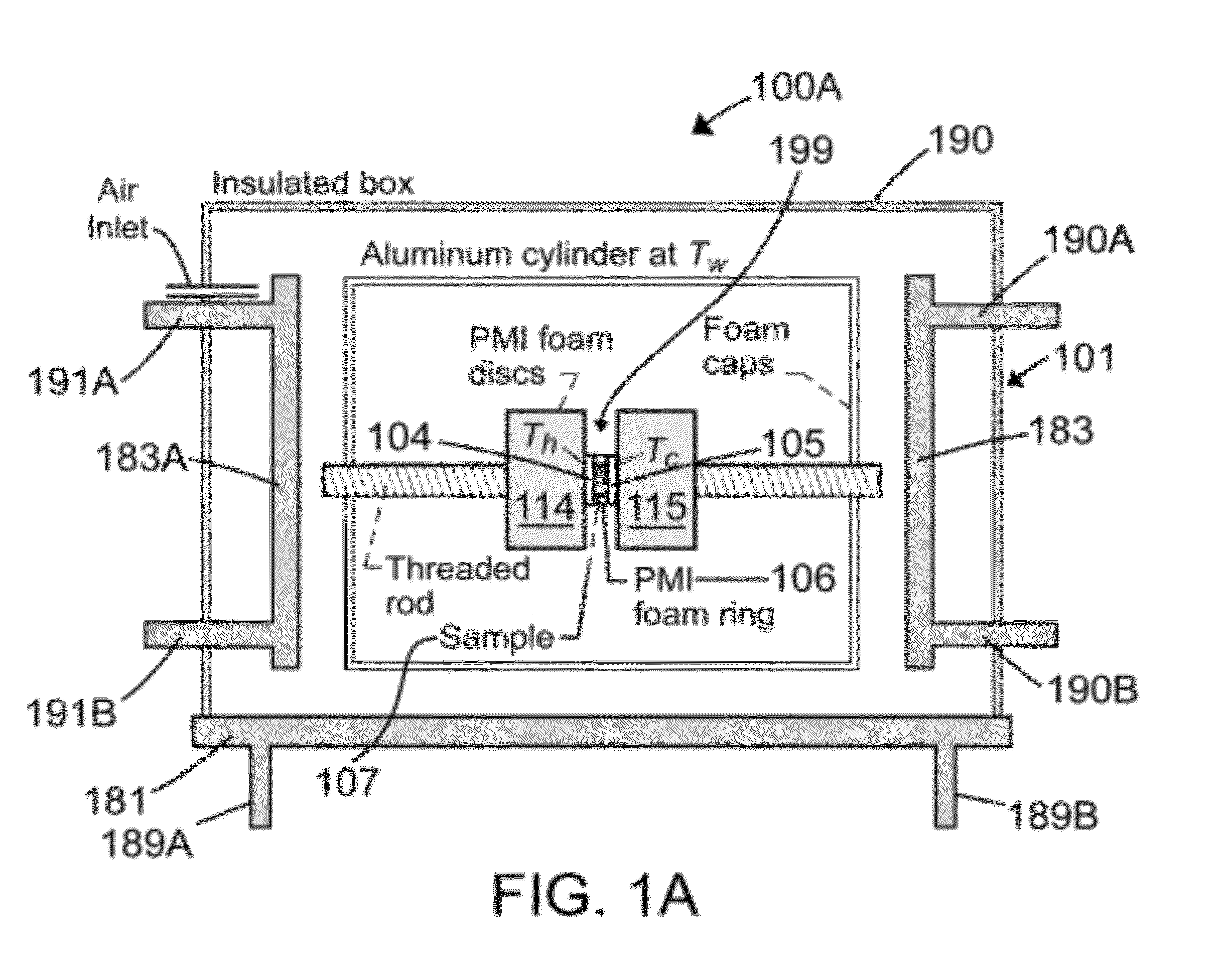
[0074]FIG. 1A is a schematic 100A of a first example 101 of a thermal conductivity measurement apparatus using a heated copper disc 104, a foam ring 106, a cooled copper disc 105, a first PMI foam disc 114 and a second PMI foam disc 115, supported within an aluminum cylinder housing with an insulated box thereover 190. FIG. 1A further illustrates an air inlet. The temperature of the air incoming is at 25° C. and is controlled by an air temperature control device (not shown). Chill plates 183, 183A are chilled (controlled to a temperature) preferably to 25° C. and communicate with a water bath through tubes 190A, 190B, 191A, and 191B, respectively. Bottom plate 181 i...


PUM


Abstract

A hot plate method and apparatus for the measurement of thermal conductivity combines the following capabilities: 1) measurements of very small specimens; 2) measurements of specimens with thermal conductivity on the same order of that as air; and, 3) the ability to use air as a reference material. Care is taken to ensure that the heat flow through the test specimen is essentially one-dimensional. No attempt is made to use heated guards to minimize the flow of heat from the hot plate to the surroundings. Results indicate that since large correction factors must be applied to account for guard imperfections when specimen dimensions are small, simply measuring and correcting for heat from the heater disc that does not flow into the specimen is preferable. The invention is a hot plate method capable of using air as a standard reference material for the steady-state measurement of the thermal conductivity of very small test samples having thermal conductivity on the order of air.

Description

FIELD OF THE INVENTION[0001]The invention is in the field of thermal conductivity measurement systems, especially those systems for measuring small samples having low thermal conductivity (highly insulating).BACKGROUND OF THE INVENTION[0002]Thermal conductivity is a physical property of fundamental importance to the developers of highly insulating materials. Standard techniques for the direct steady-state measurement of thermal conductivity, greatly influenced by a long history of test development at national standards laboratories have been established. The majority of cases described in the literature for measuring low thermal conductivity specimens (on the order of the thermal conductivity of air) use specimen sizes varying from a few hundred centimeters to over a meter. However, researchers often develop advanced, highly insulating materials in small batches with specimen sizes too small for methods normally used to directly measure thermal conductivity. An example is the develo...

Claims


Application Information

Patent Timeline
IPC IPC(8): G01N25/20
CPCG01N25/18
Inventor MILLER, ROBERT A.KUCZMARSKI, MARIA A.
Owner NAT AERONAUTICS & SPACE ADMINISTATION UNITED STATES GOVERNMENT AS REPRESENTED BY THE ADMINISTATOR OF THE
Why Eureka
Try Eureka