Gas burner

a gas burner and burner technology, applied in the field of gas burners, can solve the problems of limiting the use and performance of burners, affecting the proper prolongation and vertical positioning of venturi pipes, and reducing so as to achieve the effect of increasing the overall deliverable thermal power

Active Publication Date: 2012-07-17
ELECTROLUX HOME PROD CORP NV
View PDF22 Cites 20 Cited by
  • Summary
  • Abstract
  • Description
  • Claims
  • Application Information

AI Technical Summary

Benefits of technology

[0028]It would therefore be desirable, and is actually a main purpose of the present invention, to provide a type of gas burner provided with a central body and with a peripheral annular body separate to each other, which are provided with respective injectors and Venturi pipes, and which are not vertically placed and are able of exploiting basically the whole burner cross size (width) in order to allow the lodging of a plurality of separate Venturi pipes, increasing the overall deliverable thermal power, but still permitting adjustment of the burner to another gas set up by replacing the injectors without disassembling any part of the appliance.

Problems solved by technology

However such burners are not deprived of some drawbacks which limit their use and performances; as a matter of fact, they often show two injectors and two respective Venturi pipes, one feeding the central burner, and the other feeding the outer annular burner.
As the central burner size is unavoidably limited, it would be in any case not able of providing a high thermal power; therefore the respective gas injector and respective Venturi pipe may be limited in their extension, and so the injector and the respective Venturi pipe may normally be oriented vertical, without causing a remarkable penalization.
The case of the outer annular burner is different; in such a case, it is needed to deliver high thermal power, and this need hinders the bounds of a properly prolonged and vertically positioned Venturi pipe.
However even such conditions do not properly offer the best compromise between:the desired minimum vertical size of said gas conduits,the burner geometric shape and size, which appear to be over-sized with respect to the cooking pots / containers,and the maximization of the overall deliverable power,
Moreover, as the pipes must be lodged inside the burner, it turns that, when their number increases, the burner becomes more and more cumbersome.
This circumstance causes a performance decrease, as the heat is being transferred from the burner to the sides of the cooking pot, instead of on its bottom; as a consequence the heat transfer is obviously hindered, and the gas consumption and cooking time are experienced.
Such a solution apparently overcomes the bound due to the limited extension in the length of the gas conduit, as it makes use of the maximum available extension; however in this case too it is not possible to deliver the maximum possible power as the gas conduit is only one, being that there is not any splitting in the gas conduits implemented; as a consequence there is an apparent discrepancy between the horizontal arrangement of the gas conduit, which prolonging the Venturi pipe, increases its power, and the singleness (no splitting) of the injector and of the Venturi pipe, which prevents the full exploitation of the available room to maximize the theoretically installable thermal power.
Furthermore, the fact of placing the Venturi pipe in the centre of the lower burner portion apparently hinders, creating further functional and constructive problems, the injector assembly and the lodging of the related vertical Venturi pipe which feeds the central body and which evidently has to pass through the burner axis, which in the presently cited patent is instead taken by the horizontal Venturi pipe.

Method used


Image

  • Gas burner
  • Gas burner
  • Gas burner

Examples


Embodiment Construction

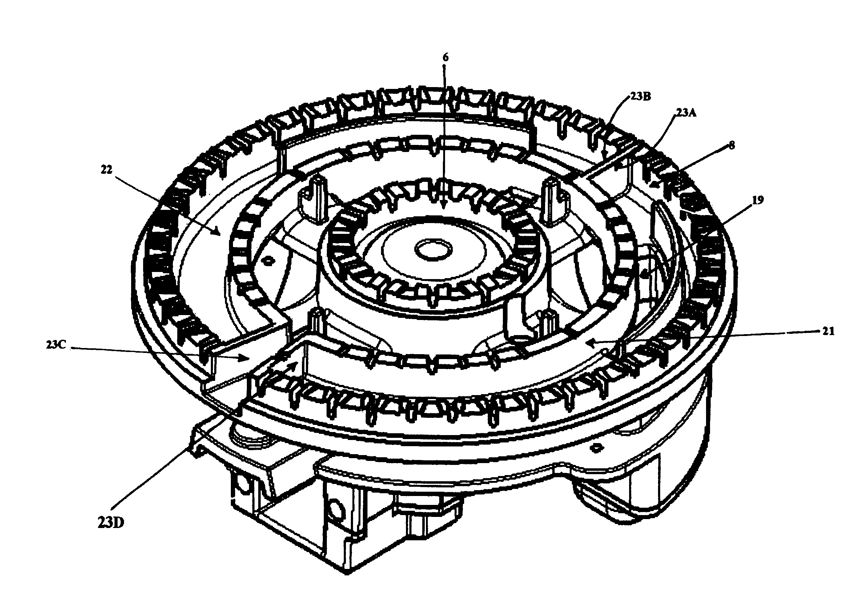
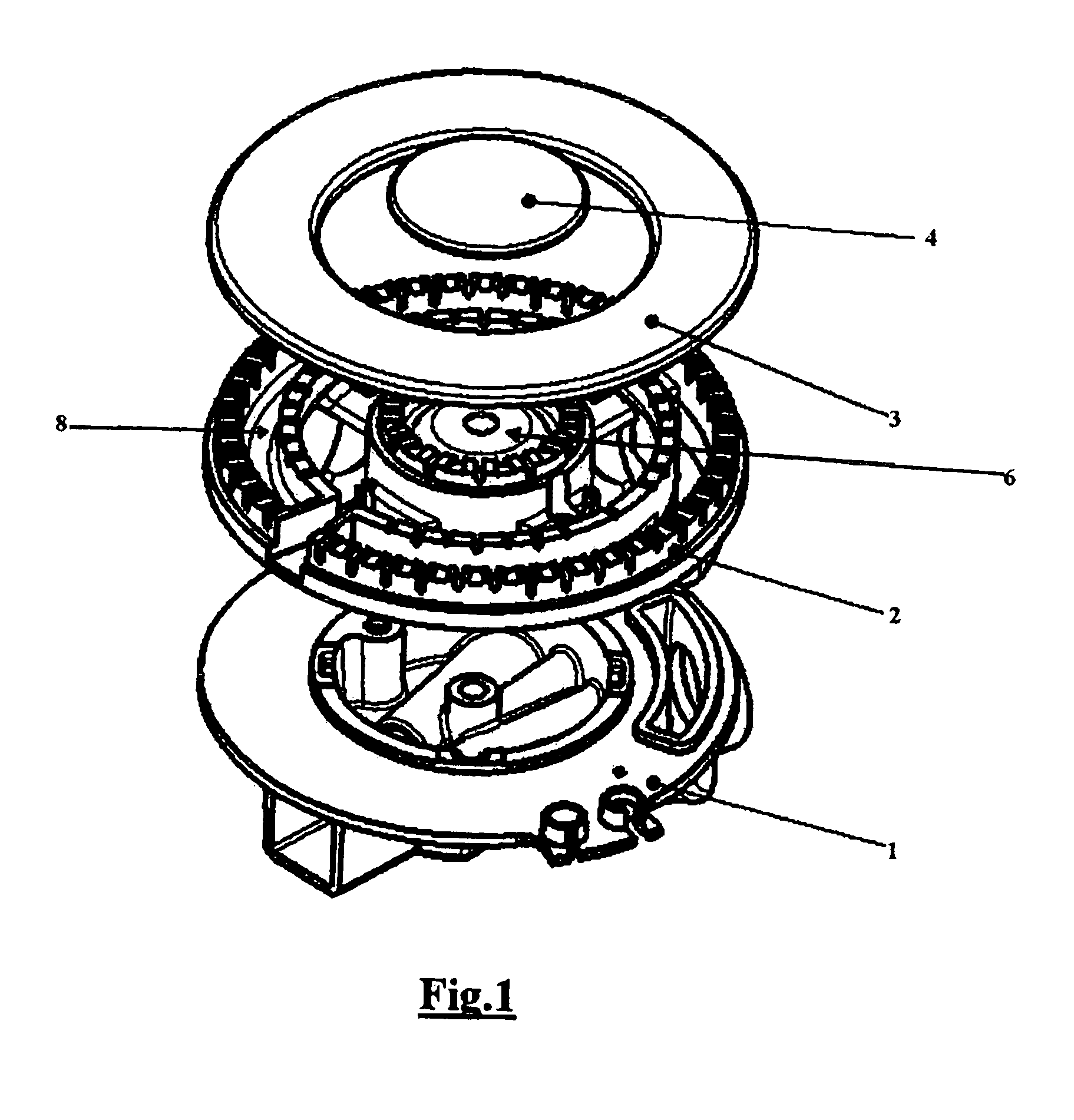
[0037]With reference to FIGS. from 1 to 6, a gas burner according to invention, and typically devoted to fit out a cooking appliance, not shown, comprises:

[0038]a burner body 1 and an upper crown 2, which are connected by the layer 5 and covers 3, 4,

[0039]a first central and circular burner 6, per se known, able of feeding a peripheral flame crown 7,

[0040]and a second annular peripheral burner 8 which surrounds the first central burner 6 at a definite distance thereof, provided with suitable adducting means to the inner flame crowns, of secondary air (B), the second annular burner having one or more flame crowns which are either inwards 9, i.e. oriented towards the first burner, or outwards 10, or both the arrangements.

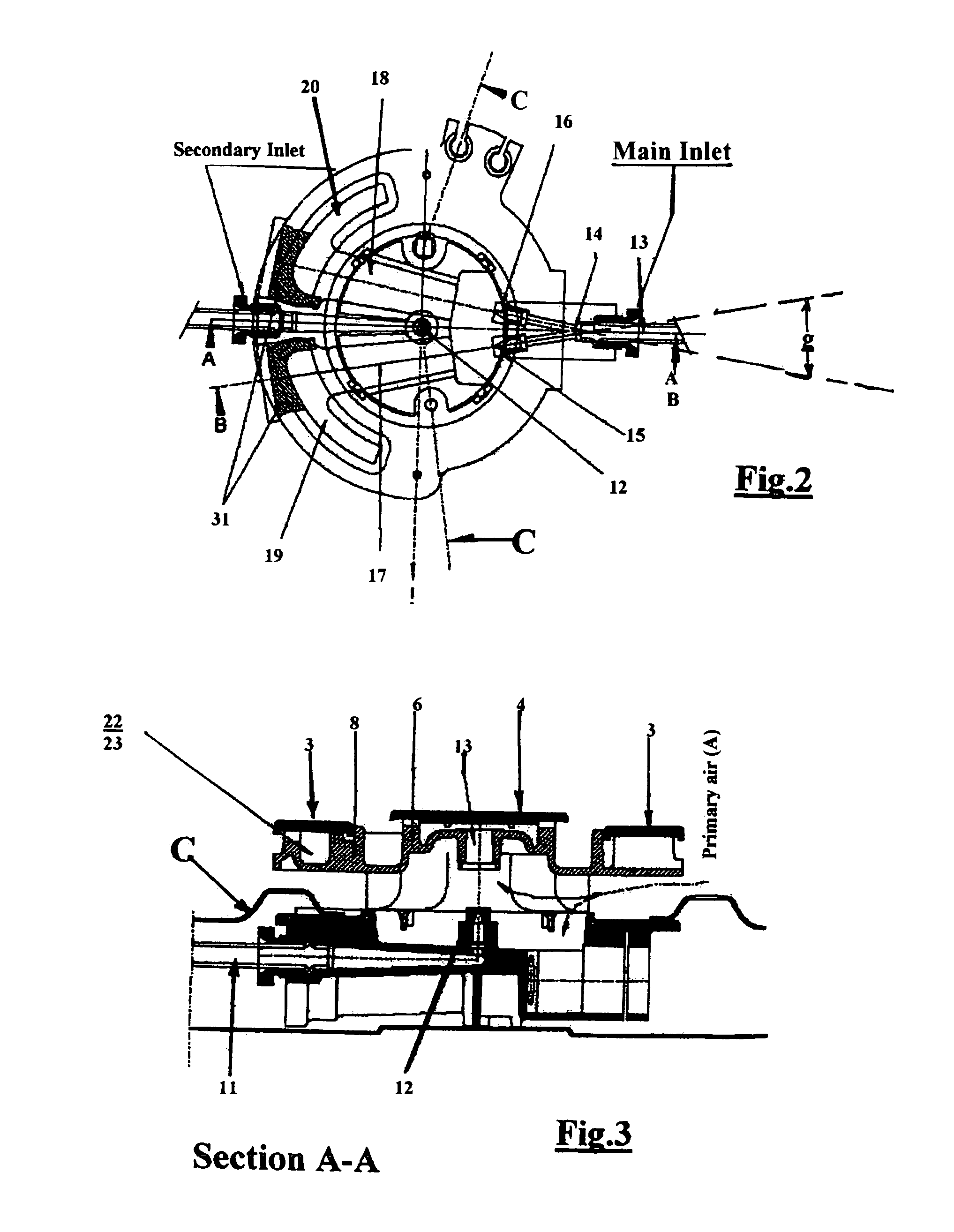
[0041]The burner body includes, in a well known way, a conduit which acts as a first gas entrance 11, which ends into a first vertically oriented injector 12 and a related first Venturi pipe 13 which is vertical as well, which are designed and arranged to feed said fi...


PUM


Abstract

Gas burner provided with a plurality of concentric flame crowns, and comprising a first central burner to supply a peripheral flame ring, a second annular burner surrounding the central burner at a defined distance and able of supplying at least a respective peripheral ring, a burner body apt to be mounted on the surface of a cooking hob, a first gas inlet in communication with the body, a first vertical gas injector, the central burner being provided with a first chamber for the diffusion of the air / gas mixture, a second gas inlet in communication with the body, wherein the second annular burner is provided with two separate chambers for the diffusion of the mixture, wherein the second gas inlet is in communication with the two separate chambers through suitable injection and conveying means, which comprise two distinct injectors in communication with the second gas inlet, and two respective horizontal Venturi pipes each of which being able of supplying with the air / gas mixture a respective of the two diffusion chambers; these are physically separate and not in communication to each other. The two horizontal and separate injectors are placed on the same end position of the second gas inlet.

Description

BACKGROUND OF THE INVENTION[0001]I. Field of the Invention[0002]The present invention relates to an improved, preferably household gas burner, generally used in the cooking gas appliances.[0003]In the following description it will be referred to as a gas burner provided with both a central body with a peripheral flame crown, and a peripheral body provided with two flame crowns, oriented inwards and outwards, but it will be intended that what is explained may be identically applied, and therefore valid, also to gas burners provided with only a peripheral body, that is without the central flame body.[0004]II. Description of the Related Art[0005]Gas burners are known that are provided with a plurality of flame crowns which assure an homogeneous distribution of the generated thermal power, and therefore provide a uniform heating of the cooking containers / pans placed over the gas burners.[0006]A particularly efficient embodiment of such burners is one which comprises a central body and a...

Claims


Application Information

Patent Timeline
Patent Type & Authority Patents(United States)
IPC IPC(8): F23D14/04
CPCF23D14/065F23D14/64F23D2900/14063F23D2900/14062F23D2900/00003
Inventor BIAGIOLI, NICOARMANNI, PIEROSTARNINI, MARCOCATALOGNE, CEDRIC
Owner ELECTROLUX HOME PROD CORP NV
Why Eureka
Try Eureka