Method for maskless particle-beam exposure

a particle beam and exposure method technology, applied in the field of maskless particle beam exposure, can solve the problems of difficult storage of complete rasterized image data, high number of pixels required to obtain a sufficiently good feature resolution at standard chip size, and general non-ideal particle optical system, etc., to limit the influence of always open or always closed apertures. , the effect of flexibleness

Active Publication Date: 2012-07-17
IMS NANOFABTION
View PDF7 Cites 109 Cited by
  • Summary
  • Abstract
  • Description
  • Claims
  • Application Information

AI Technical Summary

Benefits of technology

[0019]This solution according to the invention modifies the “trotting mode” method so as to make it more flexible and allowing an additional redundancy scheme in order to limit the influence of always open or always closed apertures. The invention is based on allowing transverse shifts of the beam image on the target, as opposed to the concept of the “trotting mode” method. In a particular aspect of the invention, after each exposure step the beam image is shifted to a different exposure position wherein the beam image, as a whole, is interlacing with the beam image at the previous position while no position of a beamlet coincides with the position of a beamlet within the beam image of the previous position. This concept is compatible with the motion of the target going on during the exposure, but at the same time allows “swinging” the image aside from the overall linear part just as much as needed to continuously cover the complete die area on the target.

Problems solved by technology

The number of pixels required to obtain a sufficiently good feature resolution at standard chip sizes is quite high and remains a challenging task.
Therefore, the storage of the complete rasterized image data is not feasible.
The particle optical system is generally non-ideal, which means that the system has imaging defects, in particular image distortions and blur variations, which additionally may very over time, temperature and image position.
A change of one of these parameters is generally not possible without altering the layout of the blanking plate.

Method used


Image

  • Method for maskless particle-beam exposure
  • Method for maskless particle-beam exposure
  • Method for maskless particle-beam exposure

Examples


Embodiment Construction

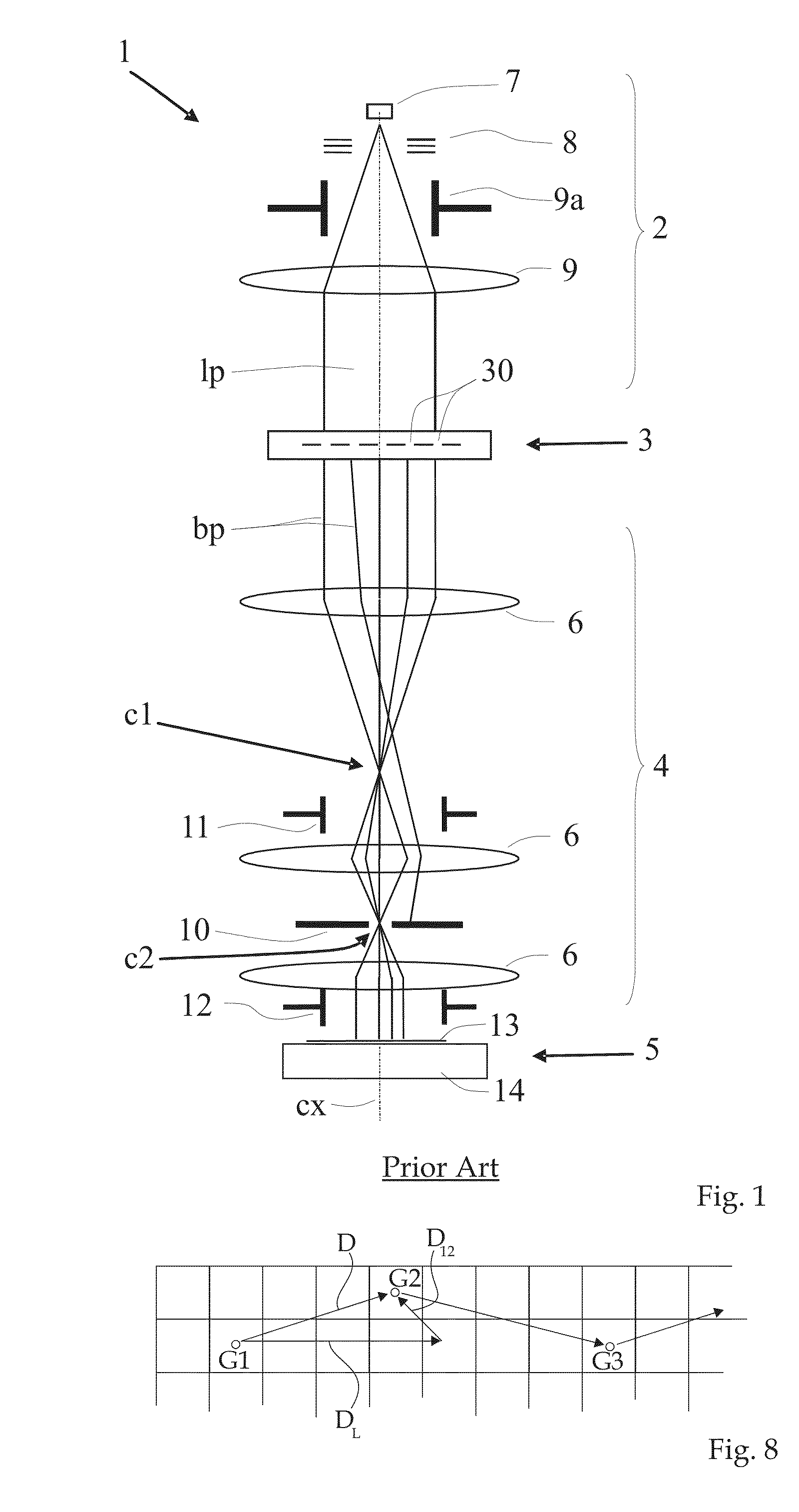
[0037]The preferred embodiment of the invention discussed in the following is a development from the PML2-type particle-beam exposure apparatus with a pattern definition (PD) system as disclosed in U.S. Pat. No. 6,768,125 and U.S. Pat. No. 7,276,714 of the assignee / applicant, and with a large-reduction projecting system. In the following, first the technical background of the apparatus is discussed—as far as relevant to the invention—, then the invention is presented in detail.

[0038]It should be appreciated that the invention is not restricted to the following embodiments or the particular layout of the PD-system, which merely represent one of the possible applications of the invention; the invention is suitable for other types of processing systems that employ a particle-beam with projector stages as well.

Maskless Particle-Beam Processing Apparatus

[0039]FIG. 1 shows a schematic overview of a maskless particle-beam processing apparatus PML2 which itself is known from prior art but i...


PUM


Abstract

In a maskless particle multibeam processing apparatus, a particle beam is projected through a pattern definition system producing a regular array of beamlets according to a desired pattern, which is projected onto a target which moves at continuous speed along a scanning direction with respect to the pattern definition system. During a sequence of uniformly timed exposure steps the beam image is moved along with the target along the scanning direction, and between exposure steps the location of the beam image is changed with respect to the target. During each exposure step the target covers a distance greater than the mutual distance of neighboring image elements on the target. The location of the beam image at consecutive exposure steps corresponds to a sequence of interlacing placement grids, and after each exposure step the beam image is shifted to a position associated with a different placement grid, with a change of location generally including a component across the scanning direction, thus cycling through the set of placement grids.

Description

RELATED APPLICATIONS[0001]This application claims priority under 35 U.S.C. §119 to European patent application number 08450184.0 filed Nov. 17, 2008, the disclosure of which is incorporated herein by reference in its entirety.FIELD OF THE INVENTION[0002]The present invention relates to a method for forming a pattern on a surface of a target by means of a beam of electrically charged particles. More in detail, embodiments of the invention can include the steps of: producing said particle beam; directing said particle beam through a pattern definition means comprising an aperture array having a plurality of regularly arranged apertures of identical shape, thus producing a number of beamlets by means of said apertures which define the shape and relative position of said beamlets, including modifying the direction of selected beamlets by means of a blanking array means of the pattern definition means to respective paths which do not meet the target, thus effectively switching off the pa...

Claims


Application Information

Patent Timeline
Patent Type & Authority Patents(United States)
IPC IPC(8): G21K5/10H01J37/08
CPCB82Y10/00B82Y40/00H01J37/3177Y10S430/143
Inventor FRAGNER, HEINRICHPLATZGUMMER, ELMARNOWAK, ROBERTBURLI, ADRIAN
Owner IMS NANOFABTION
Why Eureka
Try Eureka