Camera for mounting in motor vehicle

a technology for mounting cameras and motor vehicles, applied in the field of vehicle mounting cameras, can solve the problems of increasing installation space, device giving the driver a feeling of visual obstruction or oppression, and achieve the effect of reducing the installation space on the windshield

Active Publication Date: 2012-07-17
HITACHI ASTEMO LTD
View PDF9 Cites 57 Cited by
  • Summary
  • Abstract
  • Description
  • Claims
  • Application Information

AI Technical Summary

Benefits of technology

[0008]An object of the present invention is to provide a vehicle-mounted type of camera whose installation space on a windshield can be reduced.
[0009](1) In order to achieve the above object, the present invention is a camera for mounting in a motor vehicle, the camera comprising a substrate, an imaging unit provided on the substrate and having an optical axis in a direction perpendicular to the substrate surface, and a lens disposed on the optical axis. The camera further comprises a mirror provided on the optical axis of the imaging unit and adapted to change a direction of the optical axis to a frontward direction of the vehicle.The above configuration reduces an installation space requirement of the vehicle-mounted type of camera on a windshield.
[0015](7) In above configuration (6), the mirror is preferably retained by an attachment including a hole provided in close proximity to the mirror-retaining section, in another part of the field angle of the lens, and thus allowing the camera to obtain interior visual information of the vehicle from the hole as well as to obtain exterior visual information of the vehicle from the mirror.
[0016]According to the present invention, the installation space on the windshield can be reduced.

Problems solved by technology

For installation on the windshield, however, conventional vehicle-mounted types of cameras have had the problem that the installation space tends to increase, with the result that the installed device gives the driver a feeling of visual obstruction or a feeling of oppression.

Method used


Image

  • Camera for mounting in motor vehicle
  • Camera for mounting in motor vehicle
  • Camera for mounting in motor vehicle

Examples


first embodiment

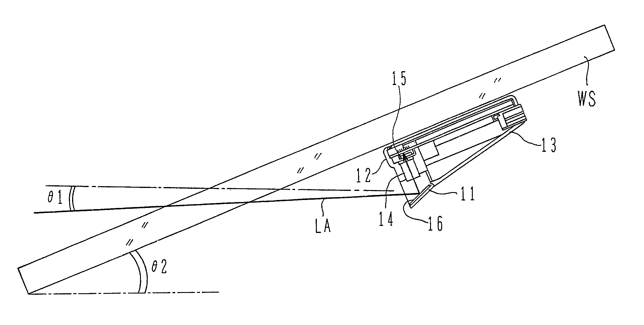
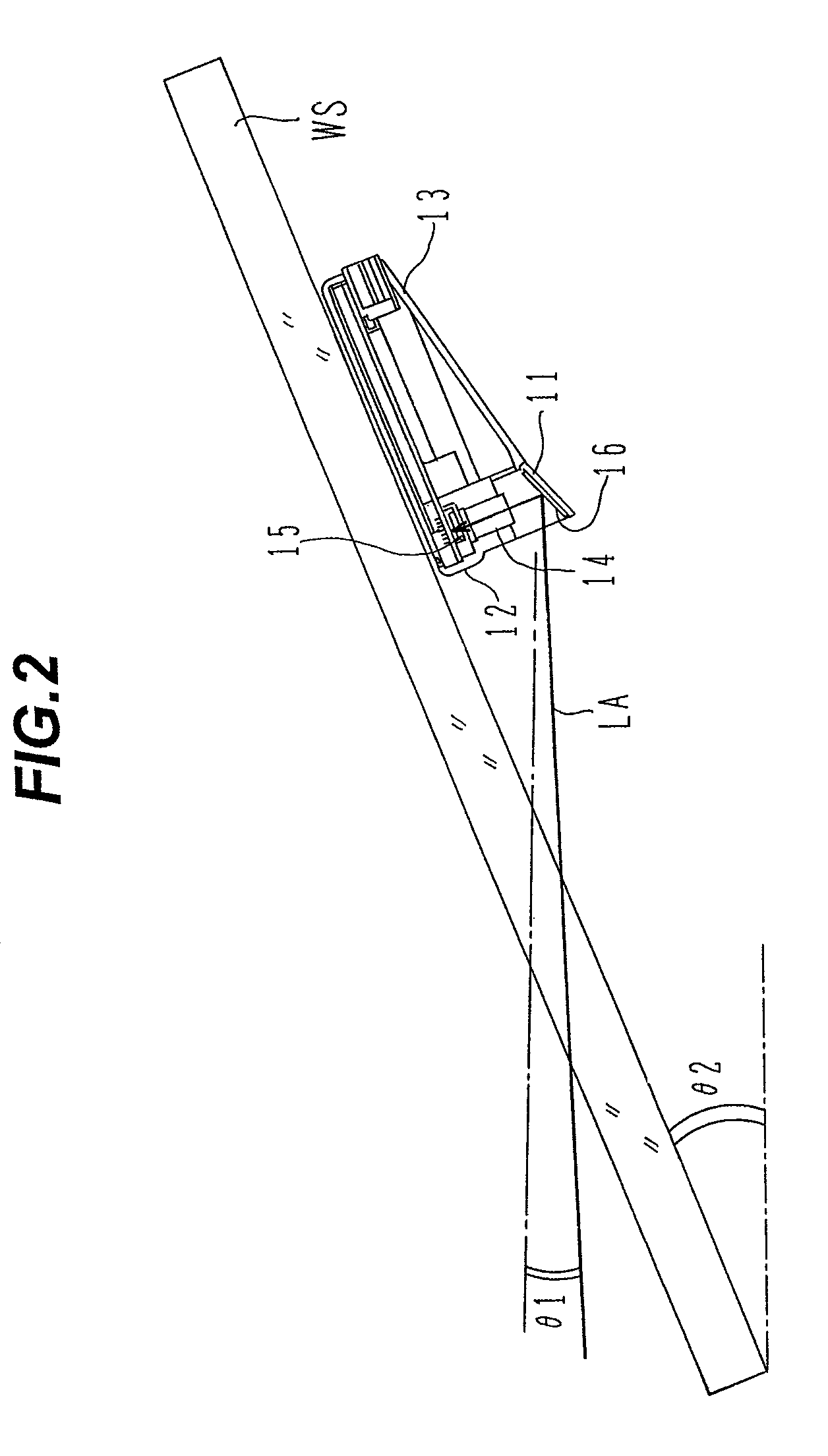
[0030]A configuration of a vehicle-mounted type of camera according to the present invention is described below using FIGS. 1 to 9.

[0031]First, an overall configuration of the vehicle-mounted type of camera according to the present embodiment is described using FIG. 1.

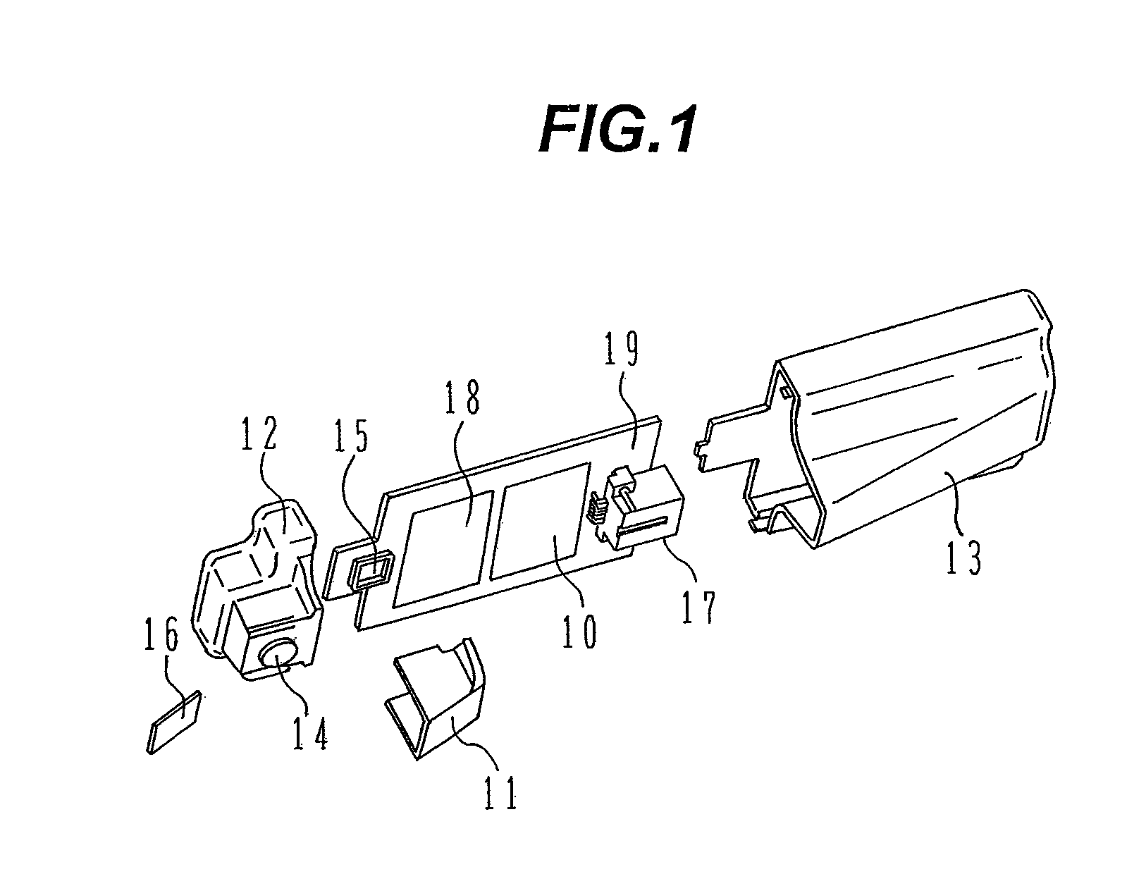
[0032]FIG. 1 is an exploded perspective view showing the overall configuration of the vehicle-mounted type of camera according to the first embodiment of the present invention.

[0033]As shown in FIG. 1, the vehicle-mounted type of camera according to the present embodiment includes: a lens 14 for constituting an optical axis; an imaging unit 15; a processing circuit 18 for processing an image that the imaging unit has acquired; a power supply circuit 10 for driving the processing circuit 18; a connector 17 used for communication as well as for supplying electric power to the camera and receiving vehicle information; a substrate 19 on which the imaging unit 15, the processing circuit 18, the power supply circuit 10, and ...

second embodiment

[0070]Next, a configuration of a vehicle-mounted type of camera according to the present invention is described using FIG. 10.

[0071]FIG. 10 is a perspective view showing the configuration of the vehicle-mounted type of camera according to the second embodiment of the present invention. In FIG. 10, the same reference numbers or symbols as used in FIG. 1 designate the same elements.

[0072]An enclosure 12A in the present embodiment is a member formed by integrating the enclosure 12 and attachment 11 shown in FIG. 1. When the installation angle of the mirror 16 is changed, the mirror itself is changed together with the enclosure 12A that is the integrated member.

[0073]As set forth above, according to the present embodiment, desired visual information can be acquired using a common enclosure, even in the vehicle-mounted type of camera more diversified in installation location or installation angle. Furthermore, the feelings of visual obstruction or oppression that may be caused to the dri...

third embodiment

[0074]Next, a configuration of a vehicle-mounted type of camera according to the present invention will be described using FIGS. 11 to 13.

[0075]Cameras designed to be installed near the windshield are in increasing demand for their vehicle-interior supervisory applications. For example, these cameras can be used to recognize the driver's or other front-seat passenger's body sizes, sitting positions on the seats, and the like, and change a way of unfolding airbags. These cameras are also useable for security purposes and can have functions such as imaging the vehicle interior for abnormalities.

[0076]First, the configuration of the vehicle-mounted type of camera according to the present embodiment is described using FIGS. 11 and 12.

[0077]FIG. 11 is a perspective view showing a configuration of an attachment used in the vehicle-mounted type of camera according to the third embodiment of the present invention. FIG. 12 is a perspective view showing the configuration of the vehicle-mounte...


PUM


Abstract

Disclosed herein is a vehicle-mounted type of camera capable of being reduced in the space required for installation on the windshield of a vehicle.An imaging unit 15 is provided on a substrate 19 and has an optical axis in a direction perpendicular to the substrate surface. The substrate 19 is set up in parallel with respect to the windshield of the vehicle. A lens 14 is disposed on the optical axis. A mirror 16 is also provided on the optical axis of the imaging unit 15, and is adapted to change a direction of the optical axis to a frontward direction of the vehicle, thus guiding frontward visual field information of the vehicle to the imaging unit 15. The mirror 16 is retained in an attachment 11. The attachment 11 can be engaged with and disengaged from an enclosure 12 that holds the lens 14.

Description

BACKGROUND OF THE INVENTION[0001]1. Field of the Invention[0002]The present invention relates generally to cameras for mounting in motor vehicles, and more particularly, to a vehicle-mounted type of camera suitable for use as a front-view camera to acquire images of objects present in a frontward direction of a vehicle.[0003]2. Description of the Related Art[0004]Vehicle-mounted types of cameras have come to be applied to vehicle-mounted systems for assisting safety driving of the vehicle in which the system is mounted, surveillance systems for detecting abnormalities and the intrusion of unwelcome persons, and other systems. Such a vehicle-mounted type of camera can process an image that the camera mounted in a vehicle has acquired, and use this processed image to extract images of on-road lane markings, traffic signposts, road markings, the immediately preceding vehicle, the opposing vehicle, persons, and the like.[0005]Several vehicle-mounted types of image-processing cameras are...

Claims


Application Information

Patent Timeline
Patent Type & Authority Patents(United States)
IPC IPC(8): H04N7/18G02B7/28H04N5/228H04N5/225H04N5/222H04N3/08
CPCB60R11/04H04N7/183
Inventor OHSUMI, KENHAYAKAWA, JUN
Owner HITACHI ASTEMO LTD
Why Eureka
Try Eureka