Device for producing vibrations

a technology of vibration and actuator, which is applied in the direction of mechanical vibration separation, bulkhead/pile preservation, etc., can solve the problems of not being able to achieve the simple guidance of the roller in the grove, the adjusting mechanism is not complicated enough, and the risk of damage is particularly high, so as to prevent the sliding of the counterweight on the bearing ring, the service life of the components is improved, and the effect of preventing foreign bodies from getting

Inactive Publication Date: 2012-07-24
THYSSENKRUPP GFT TIEFBAUTECHN
View PDF15 Cites 0 Cited by
  • Summary
  • Abstract
  • Description
  • Claims
  • Application Information

AI Technical Summary

Benefits of technology

[0023]In order to prevent wear caused by foreign bodies getting into the track, the invention preferably provides a track protector in front of and/or behind the counterweights, preferably a doctor blade stripping foreign bodies from the counterweights. Wear both of the counterweights and of the bearing ring is thereby prevented, thus significantly improving the service life of the components.
[0

Problems solved by technology

The risk of damage is particularly high in the region of the resonance frequency of the ground.
Due to the associated weight increase there is no improvement in amplitude.
For this purpose, however, neither the com

Method used


Image

  • Device for producing vibrations
  • Device for producing vibrations
  • Device for producing vibrations

Examples


Embodiment Construction

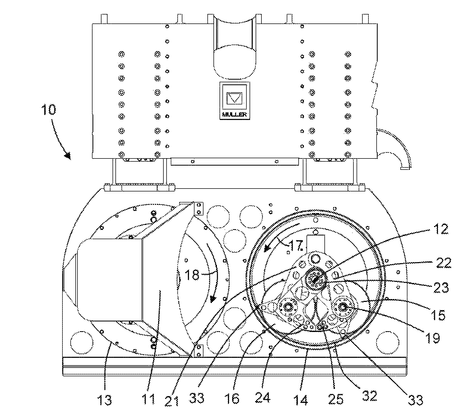
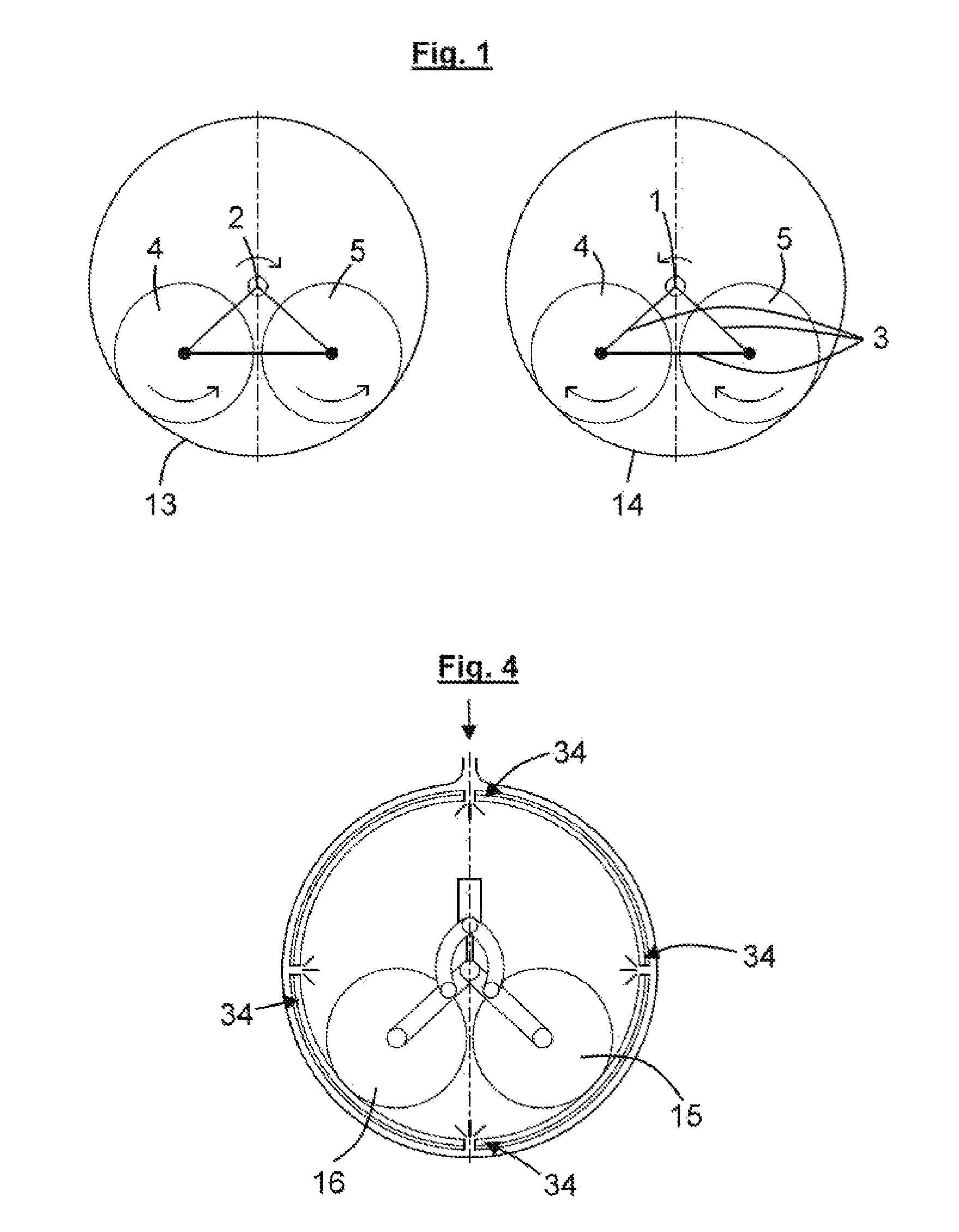
[0030]FIG. 1 shows two bearing cups 13 and 14, each comprising a pair of cylindrical counterweights 4 and 5, the counterweights of one pair are coupled to each other in a rigid manner via links 3 such that each pair acts kinetically as a single constant counterweight and may roll in the bearing cup in the direction of the arrows. The drive is carried out via a shaft 1 or 2. According to the invention both the counterweights 4 and 5 and the tracks formed by the bearing cups are comprised of a hardened material, such as a roller-bearing steel that has a hardness of HRC≧50.

[0031]The counterbalanced device 10 according to FIG. 5 has two bearing cups 13 and 14 that are centered on respective axes 11 or 12, into each of which a bearing ring 32 is incorporated. Two (or more) counterweights 15 and 16 shaped as cylinders can roll on the inner surfaces of the bearing rings 32. The bearing surfaces of the bearing rings 32 and / or of the counterweights 15 and 16 may be lubricated by a device, fo...


PUM


Abstract

The invention relates to a device for producing vibrations, particularly for fastening to ramming bodies, which are rammed into or pulled out of a burrow by said vibrations, comprising at least two balancing weights (15, 16) rotating in opposite directions in a synchronized manner and rolling on a track and driven by separate shafts. According to the invention, the track is a bearing ring (32) that is fitted into the housing, wherein said bearing ring is made of rolling bearing steel that has a hardness of HRC≧50.

Description

CROSS REFERENCE TO RELATED APPLICATIONS[0001]This application is the US-national stage of PCT application PCT / DE2008 / 001416, filed 26 Aug. 2008, published 23 Apr. 2009 as WO2009 / 049576, and claiming the priority of German patent application 102007049435.3 itself filed 16 Oct. 2007, whose entire disclosures are herewith incorporated by reference.FIELD OF THE INVENTION[0002]The invention relates to a vibratory actuator, particularly for fastening to a pile that is to be driven into or pulled out of the ground, comprising at least two counterweights that rotate in opposite directions in a synchronized manner while rolling on respective tracks and being driven by respective shafts.BACKGROUND OF THE INVENTION[0003]As is generally known, elongated profiles, such as sheet piles, tubes or the like, are driven into or pulled out of the ground with the aid of vibration. To this end use is made of vibratory actuators, also called vibration rams or vibrating units. Such vibration rams or vibrat...

Claims


Application Information

Patent Timeline
IPC IPC(8): E02D11/00E02D7/18
CPCB06B1/167E02D3/074E02D7/18
Inventor RICHTER, UWEKOECHER, JOHANNES
Owner THYSSENKRUPP GFT TIEFBAUTECHN
Why Eureka
Try Eureka