
Ignition or plasma generation apparatus

a generation apparatus and plasma technology, applied in spark plugs, machines/engines, instruments, etc., can solve the problems of complex structure, delicate adjustment of resonance means, etc., and achieve the effect of preventing or reducing the flow of reflection, facilitating the line wiring process, and mass production

Inactive Publication Date: 2012-07-24
MAGINEERING INC
View PDF13 Cites 27 Cited by
  • Summary
  • Abstract
  • Description
  • Claims
  • Application Information

AI Technical Summary

Benefits of technology

[0010]An ignition or plasma generation apparatus is provided that eliminates the need for resonance means in a combustion chamber and simplifies the electrode structure within the combustion chamber in an instance where energy from a spark discharge and microwaves is used to ignite an air-fuel mixture gas in an internal combustion engine.
[0045]Furthermore, the fourteenth aspect of the ignition or plasma generation apparatus enables the microwave energy and high-voltage pulse to be introduced into an interior of the combustion chamber via a coaxial cable and an isolator, resulting in an easier line wiring process, and making it possible to prevent or reduce a flow of a reflection of the microwave energy reversing back to the mixer.

Problems solved by technology

In an apparatus for igniting an air-fuel mixture gas in an internal combustion engine using electrical energy, resonance means requiring delicate adjustment is necessary in an instance where the air-fuel mixture gas is ignited using microwave energy alone.
Also, in an instance where energy from a spark discharge and microwaves is used to ignite the air-fuel mixture gas, a problem is presented in that an electrode for the spark discharge and an electrode for microwave radiation must both be provided in a combustion chamber, resulting in a complex structure.

Method used


Image

  • Ignition or plasma generation apparatus
  • Ignition or plasma generation apparatus
  • Ignition or plasma generation apparatus

Examples


first embodiment

[0066]An embodiment of the present invention will now be described with reference to the accompanying drawings.

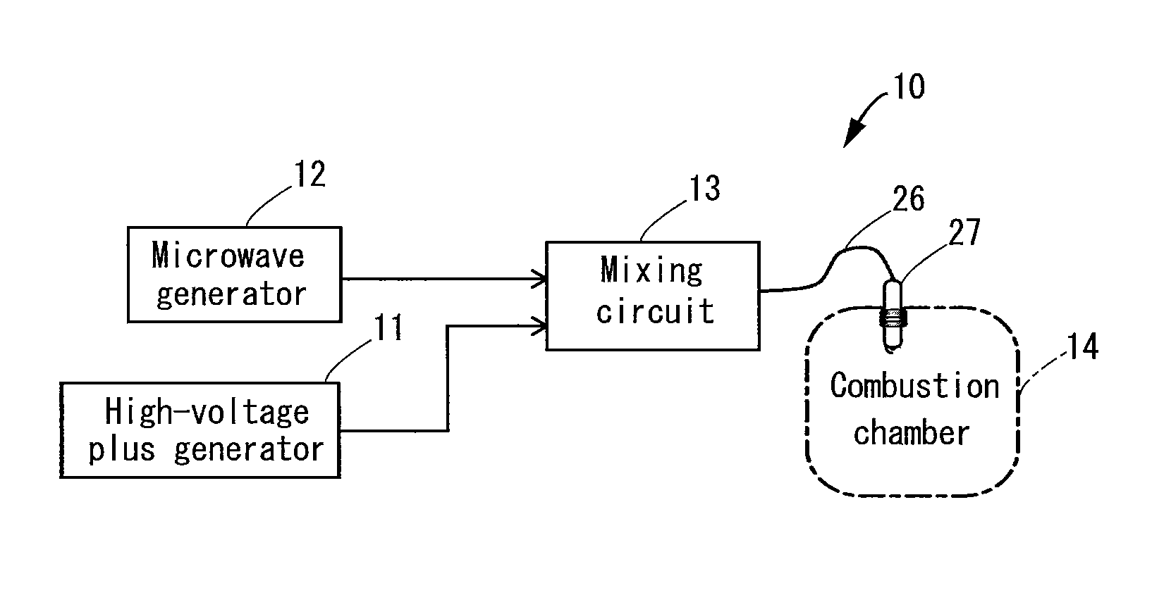
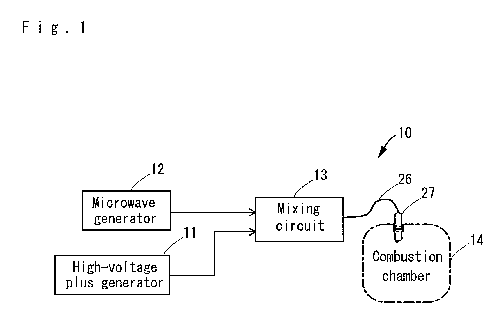
[0067]FIG. 1 shows a basic configuration of an ignition or plasma generation apparatus 10 according to a first embodiment of the present invention.

[0068]In the ignition or plasma generation apparatus 10, energy generated by each of a high-voltage pulse generator 11 and a microwave generator 12 is transmitted to a mixing circuit 13 that constitutes the mixer, as shown in FIG. 1. The mixing circuit 13 mixes the energy fed from the high-voltage pulse generator 11 and the microwave generator 12. The energy mixed in the mixing circuit 13 is supplied to an ignition plug 27 inserted into a combustion chamber 14 via a mixed output cable 26 that constitutes a transmission channel for the energy.

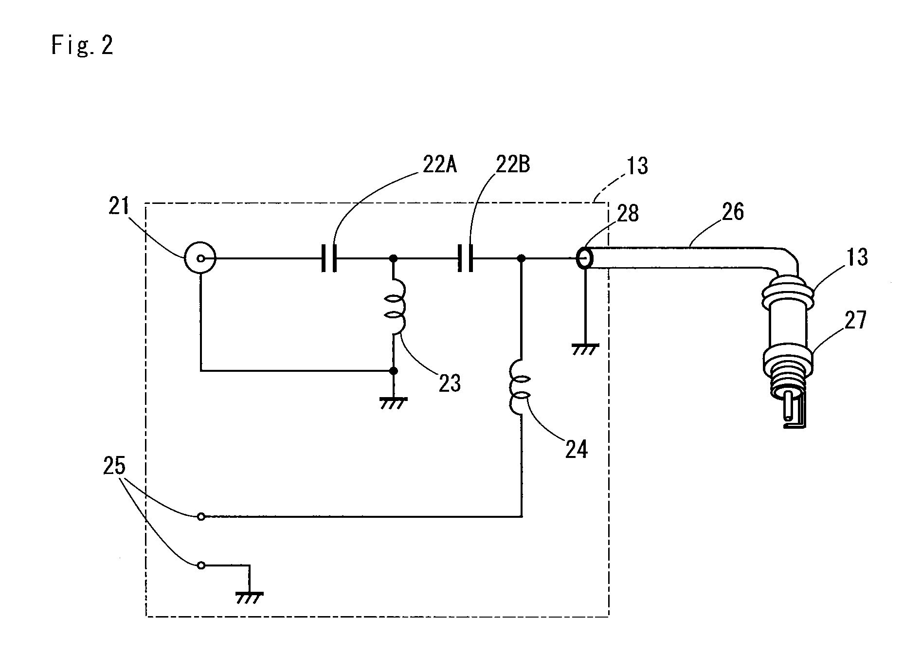
[0069]FIG. 2 shows a circuit configuration of the mixing circuit 13 in the ignition apparatus.

[0070]In the mixing circuit 13, a high-voltage pulse from the high-voltage pulse generator 11 is ...

second embodiment

[0074]FIG. 3 shows a circuit configuration of a mixing circuit 30 according to a second embodiment that can be used as a replacement for the mixing circuit 13 in the ignition or plasma generation apparatus according to the first embodiment. In the mixing circuit 30, a second input terminal 21 is connected to a primary winding of a high-frequency transformer 33 as shown in FIG. 3. One end of a secondary winding of the high-frequency transformer 33 is connected to a first input terminal 25 via a coil 34 that has a similar property to the coil 24 in the first embodiment. The connection between the one end of the secondary winding of the high-frequency transformer 33 and the coil 34 is configured so that a stray capacitance 36 is present in relation to earth. This section is therefore in a state equivalent to being earthed. As a result, the microwave energy inputted through the second input terminal 21 is transmitted to the output terminal 28 without flowing to the first input terminal ...

third embodiment

[0075]FIG. 4 shows a circuit configuration of a mixing circuit 40 according to a third embodiment that can be used as a replacement for the mixing circuit 13 in the ignition or plasma generation apparatus according to the first embodiment.

[0076]In the mixing circuit 40, a second input terminal 21 is electrically coupled to an output terminal 28 by a magnetic field coupling and an electrical field coupling connected in series, as shown in FIG. 4. In the mixing circuit 40, a second input terminal 21 is connected to a primary winding of a high-frequency transformer 43. One end of a secondary winding of the high-frequency transformer 43 is earthed, and the other end is connected to the output terminal 28 via a capacitor 44. The first input terminal 25 is connected to the output terminal 28 via a coil 45 that has a similar property to the coil 24 in the first embodiment.


PUM

PropertyMeasurementUnit
areaaaaaaaaaaa
thicknessaaaaaaaaaa
relative dielectric constantaaaaaaaaaa

Abstract

There is provided an ignition or plasma generation apparatus that eliminates the need for resonance means in a combustion chamber and simplifies the electrode structure within the combustion chamber in an instance where energy from each of a spark discharge and microwaves is used to ignite an air-fuel mixture gas in an internal combustion engine. The ignition or plasma generation apparatus includes a mixing circuit for mixing a high-voltage pulse from a high-voltage pulse generator and microwave energy from a microwave generator; and an ignition plug into which an output from the mixing circuit is supplied, the plug used for introducing the output into a combustion chamber of an internal combustion engine. The output supplied from the mixing circuit to the ignition plug is supplied in a manner in which the microwave energy and the high-voltage pulse are superimposed on each other on a same transmission line.

Description

TECHNICAL FIELD[0001]The disclosure relates to an ignition or plasma generation apparatus for performing ignition in an internal combustion engine using a combination of spark discharge and microwave energy.BACKGROUND OF THE INVENTION[0002]Ignition of an air-fuel mixture gas in an internal combustion engine is normally performed by spark discharge using an ignition plug. However, there have been proposals for a microwave ignition system that uses electromagnetic waves with a frequency of several gigahertz (GHz); i.e., microwaves, for improving combustion efficiency and other purposes.[0003]In order to reliably ignite the air-fuel mixture gas only using microwaves, an extremely strong electrical field is required; therefore, there is a need to put a cavity in a resonant state. As an attempt to resolve this problem, it was proposed in Patent References 1 and 2 for a stub structure for regulating the resonance frequency to be provided in a combustion chamber. It was proposed in Patent ...

Claims


Application Information

Patent Timeline
Patent Type & Authority Patents(United States)
IPC IPC(8): B01J19/08F02P23/00G01N27/00B01J19/12
CPCF02P3/01H05H1/24F02P23/045H01T13/50H05H1/46H05H1/52H05H1/4622
Inventor MAKITA, MINORUIKEDA, YUJI
Owner MAGINEERING INC
Learn More