Motor controlling apparatus

a technology of motor control and control device, which is applied in the direction of motor/generator/converter stopper, dynamo-electric converter control, multiple dynamo-motor starters, etc., can solve the problems of limited generated torque difference and different degrees of wear in diameter, and achieve the effect of reducing the size, mass and cost of the motor control apparatus

Inactive Publication Date: 2012-07-24
NEXGEN CONTROL SYST LLC
View PDF31 Cites 10 Cited by
  • Summary
  • Abstract
  • Description
  • Claims
  • Application Information

AI Technical Summary

Benefits of technology

[0016]In a motor controlling apparatus according to the present invention, calculation units in the controller are grouped into: the common calculation unit that calculates and outputs control signals that are common among inverters; the individual calculation unit that individually calculates and outputs control signals related to each of the inverters; and the common logic calculation unit that outputs gate signals for controlling switching of each of the inverters based on signals received from the common calculation units and the individual calculation units. Thus, operations performed by each of the calculation units are effectively grouped, and each of the calculation units, arranged in accordance with each of the motors, is effectively arranged within a controller. Therefore, the present invention achieves the effects to reduce the size, the mass, and the cost of the motor controlling apparatus.

Problems solved by technology

A technical problem in driving the induction motors together in parallel by a single inverter is in accommodating with different degrees of wear in diameters of a plurality of wheels (hereinafter, referred to as “wheel diameter”) that are driven together by a single inverter.
However, because a rated slip frequency of an induction motor is generally set in such a manner that an expectable difference in the wheel diameter does not give any influence thereto, the generated torque difference is very limited and practically does not result in a problem.

Method used


Image

  • Motor controlling apparatus
  • Motor controlling apparatus
  • Motor controlling apparatus

Examples


Embodiment Construction

[0061]A motor controlling apparatus according to an exemplary embodiment of the present invention will now be explained based on the drawings. Note that the embodiment is not intended to limit the scope of the present invention in any way.

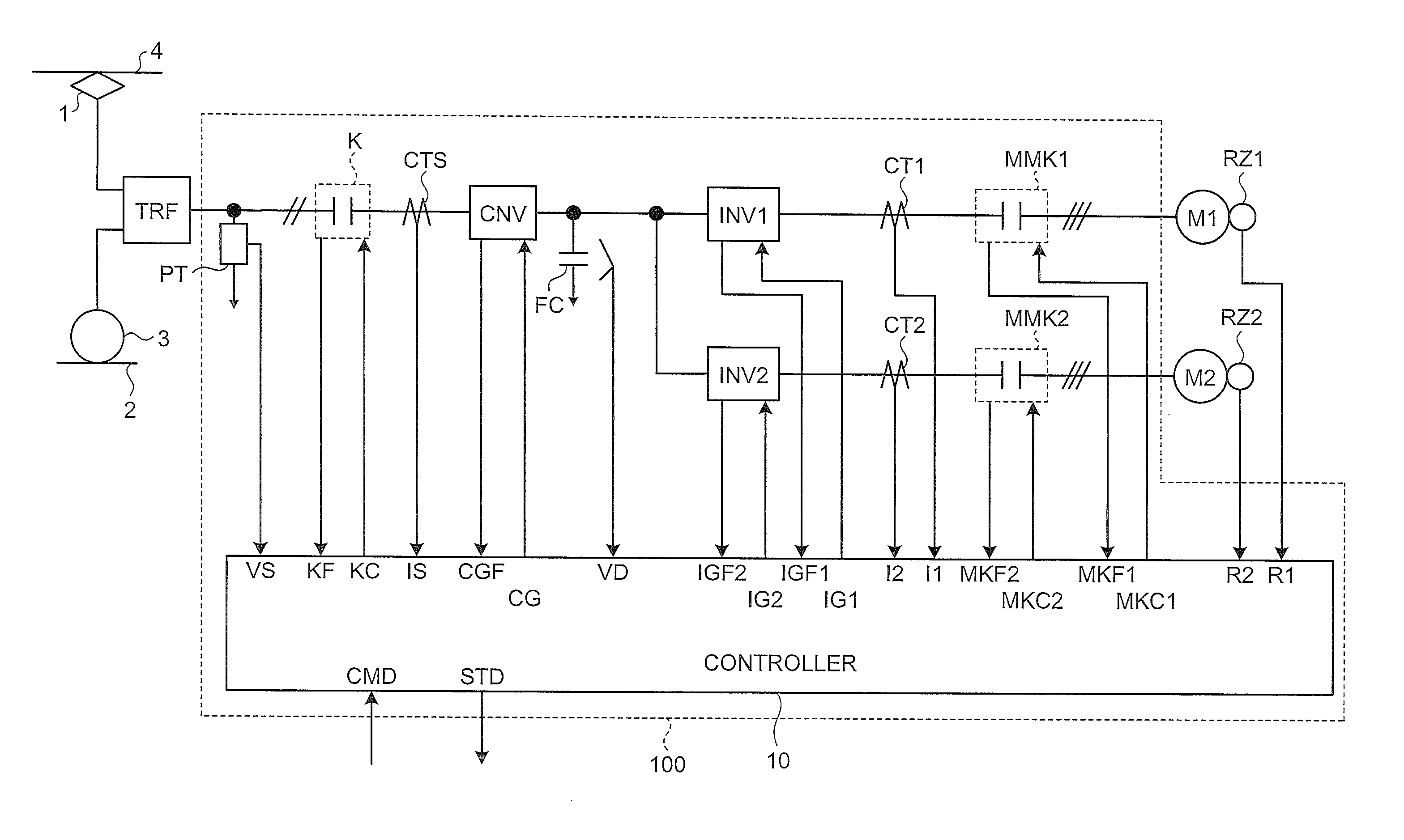
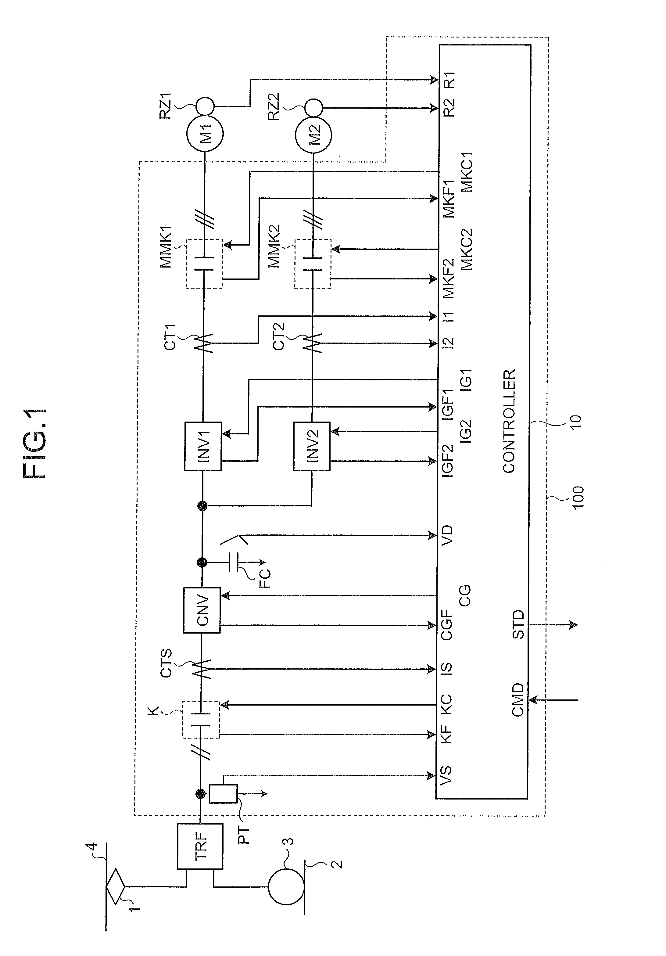
[0062]FIG. 1 is a schematic of a motor controlling apparatus according to an exemplary embodiment of the present invention. In this schematic, a controlling apparatus 100 according to the embodiment includes, sequentially from an input-stage side thereof, an input voltage detector PT, an input-side contactor K, an input current sensor CTS, a converter CNV, a filter capacitor FC, a first and a second inverters INV1 and INV2, a first and a second motor current sensors CT1 and CT2, and a first and a second motor-side contactors MMK1 and MMK2.

[0063]Furthermore, as shown in FIG. 1, the primary-side end of a transformer TRF is connected to an electric wire 4 via a power collector 1, and the other end is connected to a rail 2 that is at a ground potential...


PUM


Abstract

A motor controlling apparatus having a controller for controlling a plurality of inverters correspondingly provided to each of a plurality of alternating-current motors is reduced in size, mass, and cost by effectively grouping operations performed by each calculation unit included in the controller. This controller for controlling the inverters includes: a first common calculation unit and a second common calculation unit that calculate and output control signals that are common to each of the inverters; individual calculation units that individually calculate and output a control signal related to each of the inverters; and a common logic calculation unit 60 that outputs a gate signal for controlling switching of each of the inverters based on the signals received from the first common calculation unit, the second common calculation unit, and the individual calculation units.

Description

TECHNICAL FIELD[0001]The present invention relates to an alternating-current motor for driving an electric vehicle, and more particularly, to a motor controlling apparatus that is suitable for controlling a permanent magnet synchronous motor.BACKGROUND ART[0002]A conventional apparatus for controlling an electrically-driven vehicle generally has a structure that a plurality of induction motors, each attached to each of a plurality of axles on a truck, is driven together in parallel by a single inverter (for example, see Patent Document 1 below).[0003]A technical problem in driving the induction motors together in parallel by a single inverter is in accommodating with different degrees of wear in diameters of a plurality of wheels (hereinafter, referred to as “wheel diameter”) that are driven together by a single inverter.[0004]It is well known that the rotation speed of an induction motor (=rotor frequency) is a value obtained by adding a slip frequency to an inverter frequency. The...

Claims


Application Information

Patent Timeline
Patent Type & Authority Patents(United States)
IPC IPC(8): H02P5/74H02P5/50
CPCB60L9/32H02P5/74B60L2200/26H02H7/08H02H7/26
Inventor KITANAKA, HIDETOSHI
Owner NEXGEN CONTROL SYST LLC
Why Eureka
Try Eureka